Autotransformers
In power transmission it is sometimes necessary to interconnect electric networks whose rated voltages differ in a 2-to-1 ratio at most. An example is an interconnection of a 110-kV network and a 220-kV network. This form of interconnection is effected with the aid of a transformer or, to be more specific, an autotransformer ‘which has a higher efficiency and a smaller size than the conventional transformer of the same power rating .
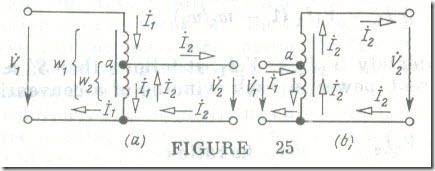
An autotransformer differs from a transformer in that it has only one electrically continuous winding that is intended for use in such a manner that part of the winding is common to both the primary (usually H.V.) and the secondary (usually L.V.) circuits, such as shown in Fig. 25 a, although the reverse arrangement, such as shown in Fig. 25 b, is also possible.
Given the primary voltage of an autotransformer and its number of turns w1 , the amplitude of the magnetic flux, Φm, in the core may be deemed fully specified, because in accord with Eq. (8.3a) and Eq. (7.2c)
V1 ≈ 4.44fw1Φm
The above approximate equality turns into a full equality in the case of an ideal transformer. In each turn of the winding, this flux induces an emf practically independent of the current in the winding.
In consequence, the voltages between the various parts of the winding are maintained constant as well.
The voltages and currents existing in an autotransformer are connected by the same approximate relations as applied to a conventional transformer [see Eqs. (8.12) and (8.19)]
V1/ V 2 ≈ wl/w2 ≈ I2/I1
The current in the common part of the winding is equal to the difference between the primary current İ1 and the secondary current
İ2 (Fig.25). As in a conventional transformer (see Fig.11), these two currents are nearly in phase. Therefore we may neglect the effect of the magnetizing (or open-circuit) current I1,oc, and deem that the rms current in the common part of the winding is │ I1 – I2 │ .
If the transformation (turns) ratio, n12 = w1/w2, only slightly differs from unity, the rms currents I2 and I1 are nearly the same and their difference, │ I2 – I1) │ , is small in comparison with each of them. Therefore the part of the winding common to the primary and secondary circuits may be wound with a finer wire, so that the cost of the windings of an autotransformer is lower than in the case of a conventional transformer and it takes up less space.
The size of a conventional transformer depends on its apparent power
ST = V1I1 ≈ V2I2
or, which is the same, on the rated apparent load power. In the case of an autotransformer, its apparent power SAT is always smaller than the load power.
The apparent power in the common part of the winning in an autotransformer (see Fig. 8.25 a) is
S’ ≈ V2 (I2 – I1) ≈ V2I2 (1 – w2/w1)
and that of the remaining part of the winding is
S‘ ≈ (V1 – V2) I1 = V1I1 (1 – w2/w1)
Since approximately V2I2 ≈ V1I1 , it follows that S’ ≈ S” ≈ SAT· The apparent power in each winding of a conventional transformer is
ST = V1I1 ≈ V2I2
Thus, given the same apparent load power, the ratio of the design apparent powers for an autotransformer and a conventional transformer is
SAT/ST = 1 – w2/w1
We may interpret it like this: The advantage arising from the use of an autotransformer increases as the difference between w2 and w1 is decreased.
To sum up, the advantages of an autotransformer decrease as the transformation (turns) ratio increases. Also, the use of an auto-transformer is warranted when the interconnection is between two voltage levels only slightly different. For example, an autotransformer may not be used for interconnecting 11 G-kV bulk supply line to a 220-V distribution network. If an attempt were ever made to do so, the insulation of the 220-V distribution network would have to be designed for 6 k V and, what is more important, such a distribution network would be an increased hazard source.
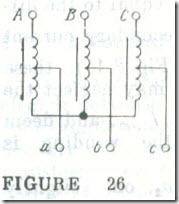
In a three-phase autotransformer it is usual to interconnect the windings into a star with the neutral brought out or to dispense with the neutral altogether (Fig. 26).
The position of the common electrical connection between the primary and secondary sides (point a in Fig. 25) can be changed at will, thereby providing a ready means for adjusting the secondary voltage, as is done in laboratory autotransformers where one of the terminals in the secondary circuit is a movable contact arm.


