Commutation in D.C. Machines
If allowed to occur, sparking under the brushes leads to a rapid destruction of the commutator, because an electric spark has a very high temperature and is capable of severely damaging the hardest metals and alloys. Therefore, the prevention of sparking under the brushes is an essential condition for a machine to have a long service life.
Sparking under the brushes may be caused by mechanical and electrical factors. The mechanical factors include a poor contact between the commutator and brushes because of a rough commutator surface or brush chatter in their boxes, etc. The electrical factors include poor commutation.
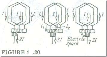
In the narrow sense, the term ‘commutation’ refers to the reversal of the current in an armature coil as it passes under a brush. In a wider sense, it refers to the processes accompanying this current reversal. Both senses can be better understood from reference to a simple lap armature winding (Fig. 1.20). The current in an armature coil must reverse during the short interval when the coil is short-circuited by a brush. This time interval is called the commutation time T. During this tune the current in the short-circuited coil must change from +I to —I , that is , by 21. As the speed of the armature is increased and the brush width bb is decreased, the commutation time becomes progressively shorter
T = bb/vc
where vc is the peripheral speed of the commutator.
If no emf wore induced in the coil undergoing commutation, the commutation process would solely be decided by the relative magnitude of the contact resistance between a brush and the two commutator bars it overlaps, with one bar gradually moving from under the brash and the other moving, as gradually, under the brush. For simplicity, we assume that the brush width is the same as the commutator bar width and that the resistance of the conductors connecting the coil to the commutator and of the coil itself is negligible in comparison with rb, which is the brush contact resistance. During commutation, a brush touches two commutator bars at a time, so there appear two contact resistances, each being greater than rb, because the area of contact between the brush and a commutator bar is now smaller than it is when the brush resides on one bar, and the contact resistance is inversely proportional to the area of contact.
In consequence, the contact resistance, rlt between the brush and the bar leaving it increases during commutation, tending to infinity at the end of the commutation time. On denoting this time as t, we
get
r1 = rbT/(T – t)
At the same time, the contact resistance between the brush and the other commutator bar decreases
r2 = rbT/t
The brush current / is shared between the two commutator bars in inverse proportion to their contact resistances
I1/i2 = r2/r1 = (T – t)/t
By Kirchhoff’s current law, the current in the coil being commutated is
I = i1 – I
and the current in the external circuit during commutation is the sum of the two currents across the two brush contact resistances
2I = i1 + i2
Hence,
2I = i1T/(T — t)
i1 = 2I (T — t)/T
and the current in the coil being commutated is
i = 2I (T— t)/T — I = I(T — 2t)/T
At the start of commutation (t = 0), this current is i = I . At the end of commutation (t = T), it is i = —I .
The current I is the current in only one parallel circuit of the armature winding. In the general case, with 2a parallel circuits the-armature current will be Iarm = 2aI. Therefore, the current in the coil undergoing commutation is
i = (Iarm/2a) (T – 2t)/T
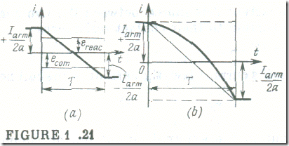
Equation (1.4) shows that under the idealized conditions assumed the current in the coil being commutated is a linear function of time (see Fig. 1.21 a). Accordingly, this form of commutation is called linear. In this ideal case the current density is the same over the entire surface area of a brush and constant for the duration of commutation. In consequence, commutation cannot give rise to sparking.
We have considered the case where the brush width bb is the same as that of a commutator bar. Actually, the brush is always several bars wide. However, this does not affect the linear form of commutation so long as no emf is induced in the coil being commutated.
In reality, however, the situation is different. The coil turns are embedded in the armature core, so the coil has a substantial inductance L. For this reason, any change in current during commutation must induce an emf of self-induction, eL, in the coil. To this emf we should add the emf of mutual induction, eM, induced by changes in the current of adjacent coils commutated at the same time. By
Lenz’s law, the two emfs oppose the change in the coil current, and retard this change. The resultant emf induced by changes of current has come to be known as the reactance emf (or voltage)
Ereac = eL + eM
It can be expressed as the emf of self-induction, Eq. (2.2), in terms of the coil inductance, Lc, and the time rate of change of current
ereac = — Lcdi/dt
The reactance emf retards the change of current (see Fig. 1.21 b) and delays the commutation for the greater part of a period, Towards the end of a period, however, when the trailing edge of the brush comes off the commutator bar, the coil current is forced to take up the value (—Iarm/2a). Thus, at the end of a period the change of current is inevitably speeded up, and this leads to an increase in the reactance emf. At the same time the current density under the brush becomes nonuniform , being substantially higher at the trailing tip of the brush, and this might cause severe heating of the brush and bar tips. Each factor may cause sparking — miniature electric arcs at the trailing edge of the brush.
The detrimental effect of the reactance emf can be minimized or even eliminated by counteracting it with a second emf, called the emf of commutation, eeom. Thus, the condition for ideal commutation is
ereac = — ecom = 0
The commutation emf is generated as the turns of the coil undergoing commutation cut an external magnetic field. In most cases, ecom is induced by the magnetic field set up by the commutating poles, Φcom = Therefore,
ecom = — wcdΦcom/dt
As the loading on the machine changes, so does the reactance emf which is proportional to the armature current. But the commutation emf also changes to the same extent and at the same time, because the compole winding is connected in series with the armature winding. Hence, a change in load does not affect the balance of ereac and ecom .
By adding more turns to the compole winding, it may be so arranged that ecom > ereac , thus leading to early commutation. Early commutation is used in machines intended for exceptionally heavy duty involving frequent reversals.
In small-size machines the necessary commutating magnetic field is set up by shifting the brushes off the q-axis (the geometric neutral axis) rather than by use of compoles. As a result of the brush shift, ecom is induced in the coil being commutated by the main magnetic field. In a generator, the brushes must be shifted in the direction of armature rotation; in a motor, they must be shifted against the direction of armature rotation (see Fig. 1.15 c).
An extremely detrimental case of unfavourable commutation is the flashover when a strong arc strikes all the way round the commutator and may even jump over to the frame, causing a severe damage to the machine. The flashover occurs as follows. A sudden change in the current of the armature coil undergoing commutation leads to a rise in the reactance emf,, and the latter initiates a strong arc between the commutator bar and the trailing edge of the brush. The arc is not extinguished, but is extended due to the rotation of the commutator, so that the commutator is shorted, and the short-circuit destroys both the commutator and brushes.


