Rotor configurations
Clearly, with so many geometric design and operational variables to consider, it is not easy to give general rules about the way the performance of a wind turbine will be affected by the values of parameters other than (perhaps) running large numbers of computer calculations. The variables for the turbine include the number of blades, blade solidity, blade taper and twist, as well as tip-speed ratio.
Blade planform
In all the preceding worked examples, a constant value of chord size was used, mainly to simplify proceedings. The actual planform used for the blades of most HAWTs is tapered, the degree of taper is chosen for structural, economic, and, to some degree, aesthetic reasons. If the planform is known or one can be specified, the calculation procedure developed previously, i.e., the BEM method, can be easily modified to include the variation of blade chord as a function of radius.
In the following section, Glauert’s analysis is extended to determine the variation of the rotor blade planform under optimum conditions.
Effect of varying the number of blades
A first estimate of overall performance (power output and axial force) based on actuator disc theory was given earlier. The choice of the number of blades needed is one of the first items to be considered. Wind turbines have been built with anything from 1 to 40 blades. The vast majority of HAWTs, with high tip-speed ratios, have either two or three blades. For purposes such as water pumping, rotors with low tip-speed ratios (giving high starting torques) employ a large number of blades. The chief considerations to be made in deciding on the blade number, Z, are the design tip-speed ratio, J, the effect on the power coefficient, CP, as well as other factors such as weight, cost, structural dynamics, and fatigue life, which we cannot consider in this short chapter.
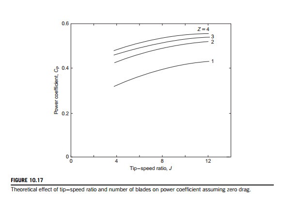
Tangler (2000) has reviewed the evolution of the rotor and the design of blades for HAWTs, commenting that, for large commercial machines, the upwind, three-bladed rotor is the industry accepted standard. Most large machines built since the mid-1990s are of this configuration. The blade number choice appears to be guided mainly by inviscid calculations presented by Rohrback and Worobel (1977) and Miller, Dugundji et al. (1978). Figure 10.17 shows the effect on the power coefficient CP of blade, number for a range of tip-speed ratio, J. It is clear, on the basis of these results, that there is a significant increase in CP in going from one blade to two blades, rather less gain in going from two to three blades, and so on for higher numbers of blades. In reality, the apparent gains in CP would be quickly canceled when blade frictional losses are included with more than two or three blades.
Tangler (2000) indicated that considerations of rotor noise and aesthetics strongly support the choice of three blades rather than two or even one. Also, for a given rotor diameter and solidity, a three-bladed rotor will have two-thirds the blade loading of a two-bladed rotor resulting in lower impulsive noise generation.
Effect of varying tip-speed ratio
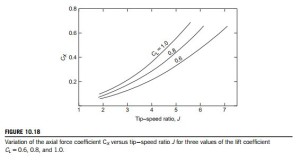
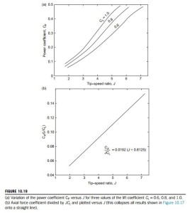
The tip-speed ratio J is generally regarded as a parameter of some importance in the design performance of a wind turbine. So far, all the examples have been determined with one value of J and it is worth finding out how performance changes with other values of the tip-speed ratio. Using the procedure outlined in Example 10.6, assuming zero drag (ε 5 0) and ignoring the correction for a finite number of blades, the overall performance (axial force and power) has been calculated for CL 5 0.6, 0.8, and 1.0 (with l 5 1.0) for a range of J values. Figure 10.18 shows the variation of the axial force coefficient CX plotted against J for the three values of CL and Figure 10.19(a) the corresponding values of the power coefficient CP plotted against J. A point of particular interest is that when CX is replotted as CX/(JCL) all three sets of results collapse onto one straight line, as shown in Figure 10.19(b). The main interest in the axial force would be its effect on the bearings and on the supporting structure of the turbine rotor. A detailed discussion of the effects of both steady and unsteady loads acting on the rotor blades and supporting structure of HAWTs is given by Garrad (1990).
Note: The range of these calculated results is effectively limited by the nonconvergence of the value of the axial flow induction factor a at, or near, the blade tip at high values of J. The largeness of the blade loading coefficient, λ 5 ZlCL/(8πr), is wholly responsible for this nonconvergence of a. In practical terms, λ can be reduced by decreasing CL or by reducing l (or by a combination of these). Also, use of the tip correction factor in calculations will extend the range of J for which
convergence of a can be obtained. The effect of any of these measures will be to reduce the amount of power developed. However, in the examples throughout this chapter, to make valid comparisons of performance the values of lift coefficients and chord are fixed. It is of interest to note that the curves of the power coefficient CP all rise to about the same value, approximately 0.48, where the cut-off due to nonconvergence occurs.
Rotor optimum design criteria
Glauert’s momentum analysis provides a relatively simple yet accurate framework for the prelimi- nary design of wind turbine rotors. An important aspect of the analysis not yet covered was his development of the concept of the “ideal windmill” that provides equations for the optimal rotor. In a nutshell, the analysis gives a preferred value of the product CLl for each rotor blade segment as a function of the local speed ratio j defined by
By choosing a value for either CL or l enables a value for the other variable to be determined from the known optimum product CLl at every radius.
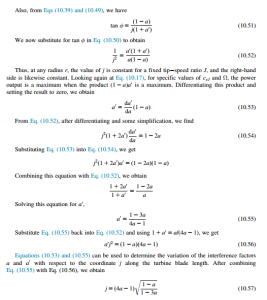
The analysis proceeds as follows. Assuming CD 5 0, we divide Eq. (10.36b) by Eq. (10.35b) to obtain
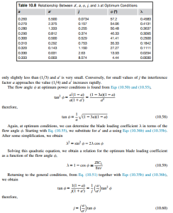
Equation (10.57), derived for these ideal conditions, is valid only over a very narrow range of a, i.e., ð1=4Þ , a , ð1=3Þ: It is important to keep in mind that optimum conditions are much more restrictive than general conditions. Table 10.8 gives the values of a0 and j for increments of a in this range (as well as φ and λ). It will be seen that for large values of j the interference factor a is
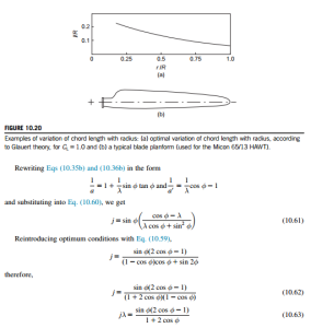
Some values of λ are shown in Table 10.8. Equation (10.62) enables j to be calculated directly from φ. These equations also allow the optimum blade layout in terms of the product of the chord l and the lift coefficient CL (for CD 5 0) to be determined. By ascribing a value of CL at a given radius, the corresponding value of l can be determined.
Figure 10.20 shows the calculated variation of blade chord with radius. The fact that the chord increases rapidly as the radius is reduced would suggest that the blade designer would ignore optimum conditions at some point and accept a slightly reduced performance. A typical blade planform (for the Micon 65/13 HAWT; Tangler et al., 1990) is also included in Figure 10.20 for comparison.
EXAMPLE 10.10
A three-bladed HAWT, with a 30 m tip diameter, is to be designed for optimum conditions with a constant lift coefficient CL of unity along the span and with a tip-speed ratio J 5 5.0.
Determine a suitable chord distribution along the blade, from a radius of 3 m to the blade tip, satisfying these conditions.
Solution
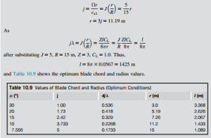
It is obviously easier to input values of φ in order to determine the values of the other parameters than attempting the reverse process. To illustrate the procedure, choose φ 5 10o, and so we determine jλ 5 0.0567, using Eq. (10.63). From Eq. (10.59), we determine λ 5 0.0152 and then find j 5 3.733. Now
