Safety Relief Valves
A relief valve for a domestic hot-water supply heater is an emergency safety device. If properly installed, it allows water to escape and spill out when excessive pressure, dangerously high temperature, or both conditions are present in the water storage tank.
It is important to understand the relationship between excessive pressure and high temperature for the safe operation of a hot-water heater. Ignorance of this relationship may result in an explosion severe enough to cause tragic loss of life and extensive property damage. The two principal causes of hot-water storage tank explosions are (1) water in the tank at an excessively high temperature, and (2) a physical weakness of the tank caused by a defect, age, corrosion, or general deterioration.
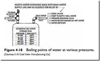
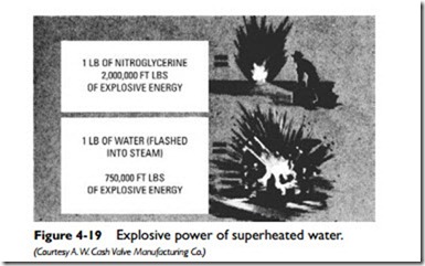
Water under pressure (greater than atmospheric pressure) can be heated above 212°F and still not boil (see Figure 4-18). As shown in Figure 4-18, the pressure in the tank will rise as it is heated because of thermal expansion. Such pressure cannot be relieved by backing into the main if the cold water is blocked by a check valve or other devices. If there is a failure in the heating-control device, the water in the tank will continue to heat beyond 212°F, and the superheated water will immediately flash into steam when a rupture occurs in the storage tank. Such action instantaneously converts 1 cubic inch of water into 1 cubic foot of steam with explosive force. This tremendous steam-flash explosive force can shoot water heaters, much like a jet-propelled rocket, through floors and roofs, burst foundations, destroy property, and cause serious or fatal injuries (see Figure 4-19).
Tests have shown that even though water pressure is raised above the normal safe tank limit, the worst that can happen is for the tank to rupture and cause water damage. When heat is applied, however, the tank becomes a potential hazard because of the steam- flash explosive possibilities. Protection against this danger can be obtained by the proper installation of suitable pressure and temperature relief valves. No water heater can operate safely without these safety relief valves.
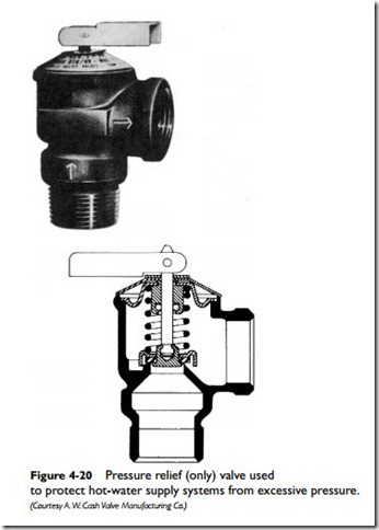
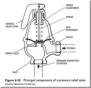
A pressure relief valve is designed to prevent excessive pressure from developing in the hot-water heater storage tank (see Figure 4-20). This is exclusively a safety device and is not intended for use as a regulating valve to control or regulate the flow pressure. This type of valve starts to open at the set pressure and requires a certain
percentage of overpressure to open fully. As the pressure drops, it starts to close and shuts at approximately the set pressure.
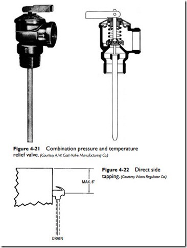
A temperature relief valve is used to prevent excessively high water temperature from developing in the hot-water heater storage tank. A temperature relief valve may be a separate unit or combined in the same housing with a pressure relief valve to form a combination temperature and pressure relief valve (see Figure 4-21).
Water heater pressure and temperature relief valves must be installed in accordance with AGA, UL, or FHA standard safety requirements. Furthermore, the pressure and temperature relief valve should be constructed and located in conformance with cur- rent American National Standard (Z21.22) listing requirements. The manufacturer’s recommendations for locating the valve on the storage tank should also be followed. Never reuse a relief valve if the water heater is being replaced. Always be sure to use the capacity relief valve recommended by the manufacturer for the installation.
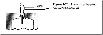
A pressure and temperature relief valve is basically a pressure relief valve with an added temperature-sensing element thermostat located at the inlet of the valve to prevent overheating or explosive dangers. The temperature-sensing element must be immersed in the water within the top 6 inches of the tank (see Figures 4-22, 4-23, and 4-24). This location is required for the immersion element because the hottest water will occupy this portion of the tank.
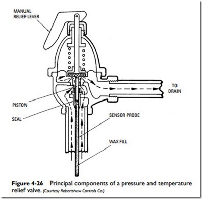
The basic components of both a pressure relief valve and a combination pressure and temperature relief valve are shown in Figures 4-25 and 4-26. Note the position of the temperature-sensing element
thermostat. When the water in the top of the tank approaches the danger zone (210°F), the thermostat expands and lifts the valve disc from the seat, allowing hot water to escape and cooler water to replace it in the tank. A decrease of less than 10° in the water tem- perature causes the thermostat to contract and allows the loading spring to reseat the valve, thus maintaining a supply of hot water at all times.
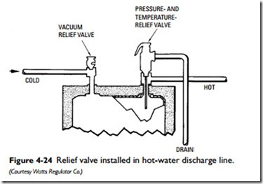
If a combination pressure and temperature relief valve is used, it should be installed in a separate tapping in the top of the hot-water storage tank (see Figure 4-24). If a separate tapping is not available, then the valve should be installed in the hot-water discharge line to
the fixture outlets at a point as close to the tank as possible (see Figure 4-24).
The relief valve should be installed in the upper end of a tee, the lower end of which is connected to the tapping in the top of the hot-water storage tank by means of a closed nipple. The hot-water supply line to the fixture outlets is then connected to the branch of the tee as shown in Figure 4-24. If the relief valve is located in the hot-water supply line to the fixtures at a distance greater than 4 inches from the storage tank, excessive temperatures generated within the tank may result in serious damage before the excessive temperature is communicated through the water and piping to the relief valve. The possibility of this situation arising can be avoided by selecting a valve with a temperature-sensing element that is long enough to extend into the top 6 inches of the tank.
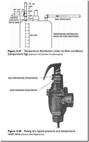
A temperature relief valve must be installed so that the temperature- sensing element is in contact with hot water in the top 6 inches of the tank. This is a necessary safety precaution because of a condition called temperature lag, that is, the condition of temperature variation between the hottest water in the top of the tank and water temperature at varying distances away from the actual tank tapping (see Figure 4-27). When the average temperature in the top 6 to 8 inches is 210°F, there will be a considerable temperature lag (under no-flow conditions) at varying distances away from the tank. For example, a temperature of 191°F can be found at a point even with the top of the tank. At 4 inches above the top of the tank, the temperature has dropped off to 170°F. Taking these conditions into account, then, it becomes clear why relief valves with extension- type temperature-sensing elements are recommended. The temperature-sensing element must reach down to the point at which the highest water temperature occurs.
Where separate pressure and temperature relief valves are used, the temperature relief valve should be installed in the top of the
hot-water storage tank or as close as possible to the tank in the hot- water supply line to the fixtures as previously described, and the pressure relief valve should be installed in the cold-water supply line at a point as close to the hot-water storage tank as possible.
The rated capacity of temperature relief valves (in Btu/h) should equal or exceed the input capacity of the hot-water heater (also expressed in Btu/h). Both the pressure and temperature steam rat- ings should be listed on the side of the valve (see Figure 4-28).
Typical piping connections for an automatic storage water heater are shown in Figure 4-29. A two-temperature capability is provided by feeding the hot water directly to the appliances. A balancing valve is installed in the cold-water line to the tempering valve to compensate for pressure drop through the heater. Because the tempering valve cannot compensate for rapid pressure fluctuations, a pressure equalizing valve should be installed where the system is subjected to water-pressure fluctuations.
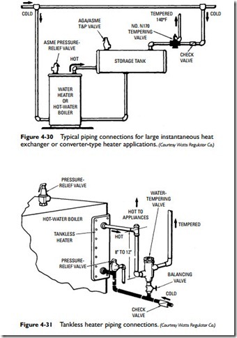
Figure 4-30 illustrates the piping connections for large-size instantaneous heat exchanger or converter heater applications. If either leg of the circulator is valved off from the heater, an ASME pressure relief valve must be installed.
Tankless heater piping connections are shown in Figure 4-31. As in other installations, a balancing valve has been installed in the cold- water line to the tempering valve to compensate for pressure drop.
