Air is the medium used for conveying heat to the various rooms and spaces within a structure heated by a warm-air furnace. It is also the principal criterion for distinguishing warm-air heat ing systems from other types in use.
The warm-air furnace is a self-contained and self-enclosed heating unit which is usually (but not always) centrally located in the structure. Depending upon the design, any one of several fuels can be used to fire the furnace. Cool air enters the furnace and is heated as it comes in contact with the hot metal heating surfaces. As the air becomes warmer, it also becomes lighter. which causes it to rise. The warmer, lighter air continues to rise until it is either discharged directly into a room (as in the so called “pipeless” gravity system), or carried through a duct system to warm-air outlets located at some distance from the furnace. After the warm air surrenders its heat, it becomes cooler and heavier. Its increased weight causes it to fall back to the furnace where it is reheated and repeats the cycle. This is a very simplified description of the operating principles involved in warm-air heat ing and it especially typifies those involved in gravity heating systems.
CLASSIFYING WARM-AIR HEATING SYSTEMS
A warm-air heating system is one in which the air is heated in a furnace and circulated through the rest of the structure
either by gravity or motor-driven centrifugal fans. If the former is the case, then the system is commonly referred to as a gravity warm-air heating system. Any system in which air circulation depends primarily on mechanical means for its motive force is called a forced warm-air heating system. The stress on the word “primarily” was intentional, because some gravity warm-air sys tems will use fans to supplement gravity flow, and this may prove confusing at first. In any event, one of the oldest forms of classifying warm-air heating systems has been on .the basis of which method of air circulation is used: gravity or forced air.
Forced warm-air heating systems are often classified accord ing to the type of duct arrangement used. The two basic types of duct arrangements used are:
1. Perimeter duct systems,
2. Extended plenum duct systems.
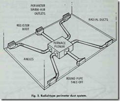
A perimeter duct system is one in which the supply outlets are located around the perimeter (i.e. the outer edge) of the structure close .to the floor of the outside wall, or on the floor itself. The return grilles are generally placed near the ceiling on the inside wall. The two basic types of perimeter duct systems are:
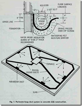
( 1) The perimeter-loop duct system (Fig. 1) ,
(2) The radial-type perimeter duct system (Fig. 2).
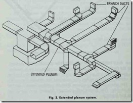
An external plenum system (Fig. 3) consis·ts of a large rectangular duct which extends straight out from the furnace plenum in a straight line down the center of the basement, attic, or ceiling. Round supply ducts connect .the plenum ·to the heat emitting units.
These and other modifications of duct arrangements are de scribed in considerable detail in Chapter 7, Volume 2 (DUCTS AND DUCT SYSTEMS).
GRAVITY WARM-AIR HEATING SYSTEMS
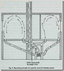
A gravity warm-air heating system (Fig. 4) consists of a properly designed furnace (with casing and smoke pipe), a warm air supply delivery system, and a cool-air return system.
In a central heating system, the warm air is delivered to the rooms and spaces being heated through a system of air ducts. the exception being a gravity floor furnace or a pipeless furnace.
Those ducts located in the basement and extending (or leading) from the furnace to the basement ceiling are referred to as leaders. The stacks are warm air ducts or pipes that connect to the leaders and extend ver·tically within .the walls and up through the build ing. The warm air enters a room .through registers located on the walls or floor (the former will generally connect to a stack; the latter to a leader).
The cooler room air exits a room by means of return grilles and .travels back ·through return air ducts to the furnace where it is reheated and recirculated.
A gravity warm-air heating system differs from the forced warm-air type by relying primarily on gravity to effect air circula tion. The operating principle of the gravity warm-air heating system is based on ·the fact that the weight per unit volume of air decreases as its temperature increases, or increases as its tem perature decreases. As ·the air is heated in the furnace, it expands and becomes lighter. Because it is lighter, it is displacecl by the cooler, heavier air entering ;the furnace. The warmer, lighter air moves 1through the leaders and up through the wall stacks where
it enters the rooms through the registers. As the air cools, it becomes heavier and returns through the return air grilles and ducts to the furnace-hence ·the name gravity warm-air heating systems.
Air circulation in a gravity warm-air heating system depends upon the difference in temperature between the rising warm air and the cooler air that is falling and returning to the furnace for reheating. The greater the difference in temperature, the faster the movement of the air; however, natural conditions will place upper limits on the speed of the air movement, making it advisable to equip a gravity type central furnace with a fan as an integral part of its construction. Such an integral fan should be powerful enough to overcome internal duct resistance to air flow, and is absolutely necessary if air filters are used in the heating system. The motive force of air circulation in a standard gravity system is not strong enough to overcome the resistance of filters.
Planning a Gravity Warm-Air Heating System
A number of different trade and professional associations will provide information for planning a gravity warm-air heating system. A very useful source of information is the most recent edition of the National Warm Air Heating and Air Conditioning Association’s Publication GRAVITY CODE AND MANUAL FOR THE DESIGN AND INSTALLATION OF GRAVITY WARM AIR HEATING SYSTEMS (Manual 5).
The following recommendations for planning such a system are offered as a basic planning guide.
1. Calculate the heat loss from each room in ·the structure.and add these together for the total heat loss.
2. Plan the leaders (i.e. the horizontal ducts or pipes lead ing from the furnace) so that none are longer than 10 ft. in length.
3. Keep the number of elbows in :the leader to a minimum.
4. Locate the warm-air outlets (registers) and return air grilles as close to the floor in each room as possible.
5. Locate the warm air outlets (registers) on the inside walls of each room and in that part of the room closest to the furnace.
6. Select warm-air and return air ducts according to their Btu carrying capacities.
7. Select a furnace capable of delivering in Btuh a register delivery equal to ,the total heat loss calculated for the structure.
8. Locate the furnace in the lowest part of the structure and as near to the center as possible.
FORCED WARM-AIR HEATING SYSTEMS
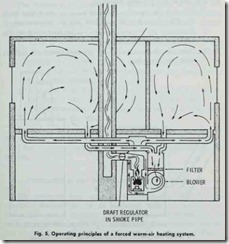
A forced warm-air heating system (Fig. 5) consists of a furnace equipped with a blower , the necessary controls, an air duct system, and an adequate number of suitably located w arm-air
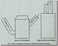
registers and cold-air returns. The warm air travels from the furnace through the supply ducts to the room registers. The cold air returns through the return-air ducts to the furnace where it is reheated and recirculated. The return-air ducts are joined together before reaching the furnace, a feature distinguishing the duct arrangement in this type of heating system from that found in heating systems relying upon the gravity flow principle of air circulation (Fig. 6).
Planning a Forced Warm-Air Heating System
ASHRAE publications (see, for example, the ASHRAE 1960 Guide) summarize design procedures for planning several types of forced warm-air beating systems. The following six elemenrts are common to each planning procedure:
1. Calculate the heat loss for each room or space, and from this data determine the total heat loss for the structure.
2. Determine the required furnace-bonnet capacity from the total heat loss of the structure.
3.Determine the location of the diffusers (warm-air outlets) on ·the building plan.
4. Calculate the required Btuh delivery of each diffuser.
5. Locate the position of the feeder ducts on the building plan.
6. Calculate the size of the feeder ducts on the basis of the total Btuh delivery it must supply.
Other elements in the design of a forced warm-air heating system will be specifically oriented to the characteristics of each system. For example, it is recommended that .the maximum length of an extended plenum (nonexistent in a forced warm-air perimeter system) not exceed 35 ft. The locations and types of warm-air outlets and return-air inlets selected for .the system will also depend upon ·the type of forced warm-air heating system used in the structure.
The following publications are recommended as being the most useful and authoritative sources of information for installing forced warm-air heating systems. In each case, the most current edition should be used.
1. WARM AIR PERIMETER HEATING (National Warm Air Heating and Air Conditioning Association. Manual 4).
2. FOUR-INCH PIPE WARM AIR PERIMETER HEAT
ING (National Warm Air Heating and Air Conditioning Association. Manual 10).
3. STANDARDS FOR THE INSTALLATION OF RESI DENCE TYPE WARM AIR HEATING AND AIR
CONDITIONING SYSTEMS (National Fire Protection Association. No. 90A).
Proprietary systems always should be installed according to the manufacturer’s instructions. Any variation from these instruc tions increase the probability of error and future problems in the system.
PERIMETER LOOP WARM-AIR HEATING SYSTEMS
The perimeter loop warm-air heating system (Fig. 1) was originally designed for use in residences built on concrete slab rather ·than over a basement. The proven success of this type of duct arrangement in providing efficient and economical . heating has resulted in its installation in all types of construction. This is rapidly becoming one of .the most popular forms of warm-air heating.
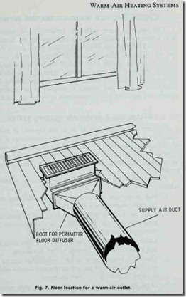
In the perimeter loop system, round ducts are imbedded in the concrete slab or suspended beneath 1the floor. The air is heated in a warm-air furnace equipped with a blower and forced through the ducts leading from the furnace to a continuous duct extending around the outer perimeter of the structure. The reg isters (diffusers) through which the heated air enters the various rooms and spaces are located along this outer perimeter duct. The most efficient operation can be achieved by placing these warm-air outlets on the floor next to the wall and beneath a window (Fig. 7). By placing the warm-air outlets here, window drafts are eliminated and the colder outside walls are kept warmed. Research shows that up to 80 percent of the heat loss from a structure can occur at these locations.
The National Warm Air Heating and Air Conditioning Asso ciation’s publication WARM AIR PERIMETER HEATING (Manual 4) is probably the most authoritative and useful source of information about this subjeot. Ask for the most recent edition, because the manual has undergone a number of revisions.
CEILING PANEL SYSTEMS
A ceiling panel system is a forced warm-air heating system in which the heated air is delivered through ducts to an enclosed space above a false ceiling. There are no air supply outlets in ·the ceiling, and the heated air is therefore blocked from direct pene tration of the occupied spaces below. Because its downward path is blocked, the heated air spreads over the entire surface area of the false ceiling. The ceiling eventually absorbs the heat and the cooler air is returned to the furnace for reheating and recirculation. The heat is transferred from the ceiling to the occupied spaces by radiation. A more appropriate name for this type of panel heating system might be “ceiling space panel system.” Other types of ceiling panel systems are described in Chapter 1, Volume 3 (RADIANT HEATING).
A ceiling panel system of this type does not differ from the standard forced warm-air heating system except in 1he design of the heat emitting unit. Instead of using compact (individual heat emitting units) a ceiling panel system uses a portion of the struc ture itself. As a result, considerable experience is necessary to install this type of heating system. It is only recommended for new construction, and never as a conversion from an exis:ting heating system.
ZONING A FORCED WARM-AIR HEATING SYSTEM
The design of some residences, particularly the larger split level homes, often causes balancing problems for the heating sys tem. As a result, certain rooms will remain much colder than the rest of the house. This is a problem that cannot be corrected simply by turning up the heat, because the rest of the house will become .too hot. The most effective solution is to divide the heating system into two separate zones, each controlled by its own thermostat. A motorized damper is installed in the existing duct system, and regulated by the thermostats to obtain the balance.
BALANCING A WARM-AIR HEATING SYSTEM
It is not always necessary to go to the expense of zoning to insure that each room receives enough heat. Sometimes a heating system can be balanced by reducing the air delivery to rooms or sections of the structure that require less heat. This results in automatically diverting more air and heat to those areas that require it.
The procedure for balancing a warm-air heating system is as follows:
1. Pick a day for balancing the system when the outdoor dry-bulb temperature is 40 °F or below.
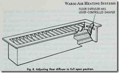
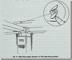
2. Open the dampers in all warm-air outlets as wide as pos sible (Fig. 8). The same holds true if the dampers are in the supply ducts (Fig. 9).
3. Leave the thermostat at one setting for at least three hours, and make certain the furnace blower is running.
4. Check the temperatures in all rooms. This can be done with thermometers (if you are certain they register equally), or simply by making your own judgment.
5. Leave the dampers in the coldest rooms wide open, and adjust the dampers in the warmer rooms to obtain the desired balance. After each adjustment, allow the system to stabilize for at least 30 minutes before checking the temperature or making the next adjustment.
When balancing a heating system, do not expect immediate results. A little patience makes it well worth the effort.
