Actuator disc approach
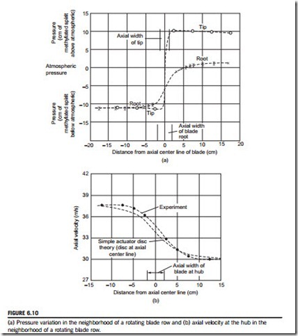
In the radial equilibrium design method it was assumed that all radial motion took place within the blade row. However, in most turbomachines of low hub-tip ratio, appreciable radial velocities can be measured outside of the blade row. Figure 6.9, taken from a review paper by Hawthorne and Horlock (1962), shows the distribution of the axial velocity component at various axial distances upstream and downstream of an isolated row of stationary inlet guide vanes. This figure clearly illustrates the appreciable redistribution of flow in regions outside of the blade row and that radial velocities must exist in these regions. For the flow through a single row of rotor blades, the variation in pressure (near the hub and tip) and variation in axial velocity (near the hub), both as functions of axial position, are shown in Figure 6.10, also taken from Hawthorne and Horlock. Clearly, radial equilibrium is not established entirely within the blade row.
A more accurate form of flow analysis than radial equilibrium theory is obtained with the actuator disc concept. The idea of an actuator disc is quite old and appears to have been first used in the
theory of propellers; it has since evolved into a fairly sophisticated method of analyzing flow problems in turbomachinery. To appreciate the idea of an actuator disc, imagine that the axial width of each blade row is shrunk while, at the same time, the space-chord ratio, the blade angles, and overall length of machine are maintained constant. As the deflection through each blade row for a given incidence is, apart from Reynolds number and Mach number effects (cf. Chapter 3 on cascades), fixed by the cascade geometry, a blade row of reduced width may be considered to affect the flow in exactly the same way as the original row. In the limit as the axial width vanishes, the blade row becomes, conceptually, a plane discontinuity of tangential velocity—the actuator disc. Note that while the tangential velocity undergoes an abrupt change in direction, the axial and radial velocities are continuous across the disc.
An isolated actuator disc is depicted in Figure 6.11 with radial equilibrium established at fairly large axial distances from the disc. An approximate solution to the velocity fields upstream and downstream of the actuator can be found in terms of the axial velocity distributions far upstream and far down- stream of the disc. The detailed analysis exceeds the scope of this book, involving the solution of the
equations of motion, the equation of continuity, and the satisfaction of boundary conditions at the walls and disc. The form of the approximate solution is of considerable interest and is quoted here.
For convenience, conditions far upstream and far downstream of the disc are denoted by sub- scripts N1 and N2, respectively (Figure 6.11). Actuator disc theory proves that at the disc (x 5 0), at any given radius, the axial velocity is equal to the mean of the axial velocities at N1 and N2 at the same radius, or
Subscripts 01 and 02 denote positions immediately upstream and downstream, respectively, of the actuator disc. Equation (6.41) is known as the mean-value rule.
In the downstream flow field (x $ 0), the difference in axial velocity at some position (x, rA) to that at position (x 5 N, rA) is conceived as a velocity perturbation. Referring to Figure 6.12, the axial velocity perturbation at the disc (x 5 0, rA) is denoted by Δ0 and at position (x, rA) by Δ. The important result of actuator disc theory is that velocity perturbations decay exponentially away from the disc. This is also true for the upstream flow field (x # 0). The result obtained for the decay rate is
At the disc, x 5 0, Eqs (6.43a) and (6.43b) reduce to Eq. (6.41). It is of particular interest to note, in Figures 6.9 and 6.10, how closely isolated actuator disc theory compares with experimentally derived results.
Blade row interaction effects
The spacing between consecutive blade rows in axial turbomachines is usually sufficiently small for mutual flow interactions to occur between the rows. This interference may be calculated by an extension of the results obtained from isolated actuator disc theory. As an illustration, the simplest case of two actuator discs situated a distance δ apart from one another is considered. The extension to the case of a large number of discs is given in Hawthorne and Horlock (1962).
Consider each disc in turn as though it was in isolation. Referring to Figure 6.13, disc A, located at x 5 0, changes the far upstream velocity cxN1 to cxN2 far downstream. Let us suppose for sim- plicity that the effect of disc B, located at x 5 δ, exactly cancels the effect of disc A (i.e., the veloc- ity far upstream of disc B is cxN2, which changes to cxN1 far downstream). Thus, for disc A in isolation,
Now the combined effect of the two discs is most easily obtained by extracting from the preceding four equations the velocity perturbations appropriate to a given region and adding these to the
Figure 6.13 indicates the variation of axial velocity when the two discs are regarded as isolated and when they are combined. It can be seen from these equations that as the gap between these two discs is increased, the perturbations tend to vanish. Thus, in turbomachines where δ/r is fairly small (e.g., the front stages of aircraft axial compressors or the rear stages of condensing steam turbines), interference effects are strong and then the simpler radial equilibrium analysis is inadequate.
Application to compressible flow
An elegant analysis to the problem of compressible flow through a multistage turbomachine has been developed by Lewis (1995) using an innovative application of actuator disc theory, which models the influence of density gradients on the meridional flow through the turbomachine. The analysis takes advantage of previous solutions for the flow induced by source discs and the analogy between compressible flows and incompressible flows with source distributions. The following con- clusions were drawn by Lewis:
1. Vortex actuator disc theory can be extended to include compressibility effects, which may be superimposed linearly upon rotational effects. The influence of density gradients upon the meridional flow is considerable for typical free-vortex axial turbine stages.
2. Plane actuator discs can be easily replaced by smeared actuator discs distributed uniformly between the leading and trailing edge planes of each blade row.
3. A simple analysis extending cylindrical compressible actuator disc theory to axial turbines with
flared annuli has been completed for application to multistage turbines.
4. The method is ideal for rapid computational analysis.
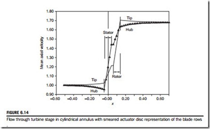
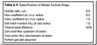
Figure 6.14 illustrates the predicted axial velocity distribution at the hub and tip radii of a model turbine stage (Table 6.4 gives the main details) resulting from axially smeared actuator discs to rep- resent the blade rows. This smearing spreads the density gradient fairly realistically between the blade leading and trailing edges. The rather large change in axial velocity observed is the result of the overall decrease in density—the stage chosen was cylindrical. Usual design practice would be to increase the annular area to maintain a more or less constant value of axial velocity.


