Thermostat Terminal Identification
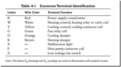
The National Electrical Manufacturers Association is at present attempting to standardize thermostat markings in order to aid the installer in wiring and servicing. Thermostat terminals have been given standard identification letters that specify the function of the terminal. These identification letters are also matched, in most cases, with the color-coding of the wire. A partial list of equivalent terminal markings is given in Table 4-1.
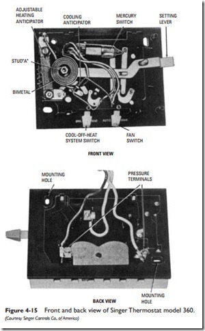
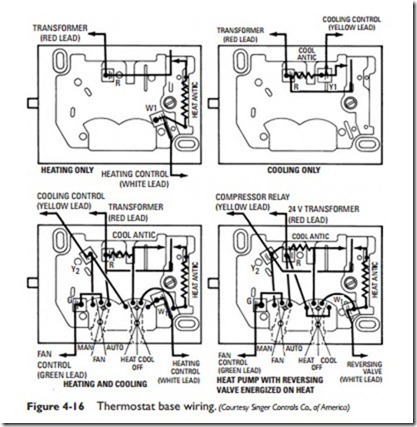
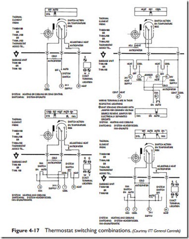
Thermostat installation literature will generally contain at least one internal view and/or wiring diagram in which the various terminals are identified by a specific letter.
Thermostat Anticipators
A thermostat anticipator is a device used to reduce the operating differential of the heating or cooling system. It is designed to enable the thermostat to shut off the furnace or boiler slightly in advance of the actual set temperature. As a result, the thermostat shuts off the heating equipment sooner than it would if it were affected by only the room temperature, thereby compensating for heat transfer lag. A thermostat may be equipped with a heat anticipator, a cold anticipator, or both.
A heat anticipator is a small resistor (resistive heater) connected in series with the switch inside the thermostat. Heat generated by the resistor when the switch is in the on position heats the thermo- stat bimetal actuator and causes the internal temperature of the thermostat to rise faster than the surrounding room temperature.
Thermostats are available with fixed anticipators, plug anticipa- tors, or variable anticipators.
A fixed heat anticipator must be sized in accordance with the amperage or current draw of the operating valve in order to secure the correct degree of heat anticipation. These anticipators are generally available in the range of 0.1 to 1.5 amperes. When using a thermostat equipped with a fixed heat anticipator, check the nameplate on the valve or relay to make certain the ampere rating does not exceed the maximum amp (current) draw. For example, if the thermostat is equipped with a 0.40- to 0.60-ampere fixed heat anticipator, the valve or relay should not exceed 0.60 ampere.
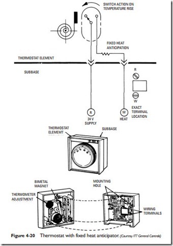
The thermostat shown in Figure 4-20 is an example of one equipped with a fixed heat anticipator. The anticipator is contained in the thermostat element along with the magnetic switch and a room temperature thermometer.
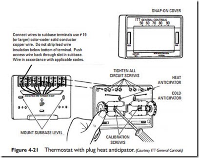
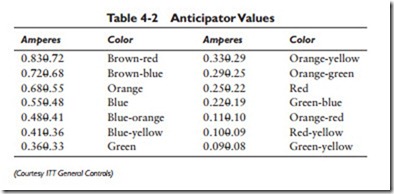
Figure 4-21 illustrates a thermostat equipped with a plug-type heat anticipator. This design offers some degree of latitude in selecting a
proper anticipator. The current (amps) drawn by the primary control or valves is first determined, and an anticipator having the proper value is selected from among those listed in Table 4-2. The heating cycle can be lengthened by selecting an anticipator one step above the proper value. Shorter cycles can be obtained by selecting an anticipator one step below the proper value.
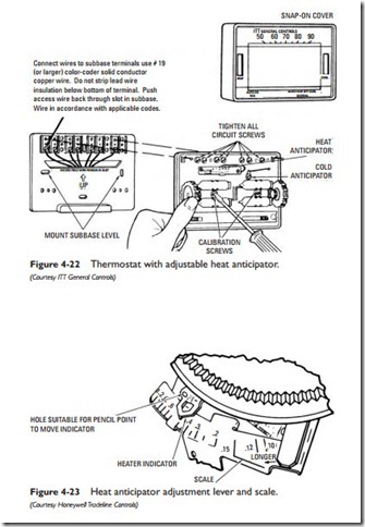
Thermostats with adjustable (variable resistance) heat anticipators can be adjusted over a range of approximately 0.1 to 1.5 amperes (see Figure 4-22). Before making any adjustments, you should first read the equipment manufacturer’s instructions for selecting proper anticipator values.
Heat anticipator adjustments are made on a thermostat with an indicator or adjustment lever that moves along a scale (see Figure 4-23). Adjustments are made in accordance with the values marked along this scale.
As with the plug-type heat anticipator (see Figure 4-21), the cur- rent (amps) drawn by the primary control or valve must be deter- mined first. In a gas-fired heating system, the heat anticipator should be set to correspond to the secondary (thermostat) current of the valve or relay. In an oil-fired heating system, the heat anticipation indicator should be set 0.15 ampere higher than the rated secondary current of the relay.
The anticipator adjustment lever should be moved only 1⁄4 to 1⁄2 scale division at a time. Never move or set the lever more than 11⁄2 scale divisions under the valve or relay current ratings. Longer on periods can be obtained by setting the adjustment lever at a slightly
higher amp value. For shorter on periods, set the lever at a slightly lower amp value.
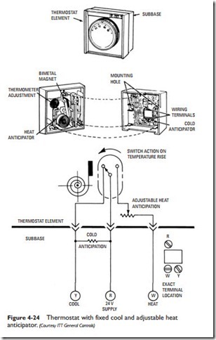
The cold anticipator for the thermostat shown in Figure 4-24 is not adjustable and should not be changed. The same is true of the other thermostats. Only fixed cold anticipation is used. Furthermore,
on cooling thermostats, the cold anticipation is in parallel with the cooling contacts so that anticipation heating occurs while the cooling unit is off.

