One-Pipe, Divided-Circuit Nonrelief System
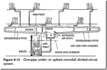
The one-pipe, divided-circuit nonrelief system differs from the one just described in that there are two mains at the high point taken off by a tee as in Figure 8-13. These mains terminate in a U-shaped drip connection (LF) at the low point. Each should be vented with a quick vent as shown. Evidently each main takes care of only half the total condensate.
This steam heating system is suited to long buildings with a boiler located near the center. The end of each main is connected to a separate drip pipe connected with a common return, giving sepa- rate seals for each end.
For proper operation, these ends should not be at a lower eleva- tion than 14 in above the boiler water line. The individual seals make the two halves of the divided circuit independent, which is desirable for unequal loads. Thus, there may be considerable differ- ence between the pressure at L and F, each being what is necessary to balance the load.
One-Pipe Circuit System with Loop
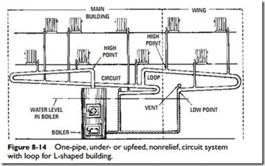
The one-pipe circuit system with loop is adapted to L-shaped buildings, a circuit being used for the main building and a loop (tapped from the circuit) servicing the wing (Figure 8-14). The mains are
installed for the proper drainage of the condensation by providing two high points—one at the beginning of the circuit and the other at the beginning of the loop—thus giving ample margin above the boiler water line for adequate pitch in both the circuit and the loop. This is clearly shown in Figure 8-14.
The low point of the loop is higher than the low point of the circuit because the pressure at the end of the loop is less than the pressure at the end of the circuit. This requires a longer vertical drip pipe since the liquid column rises higher to balance the lower pressure.

