The Transistor
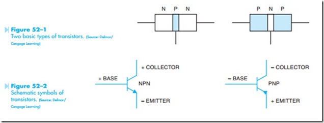
Discuss the operation of a transistor Connect a transistor in a circuit Transistors are made by joining three pieces of semiconductor material together. There are two basic types of transistors, the NPN and the PNP, Figure 52–1. The schematic symbols for these transistors are shown in Figure 52–2. The difference in these transistors is the manner in which they are connected in a circuit. The NPN transistor must have positive connected to the collector and negative connected to the emitter. The PNP must have positive connected to the emitter and negative connected to the collector. Notice that the base must be connected to the same polarity as the col- lector to forward bias the transistor. Also notice that the arrows on the emitters point in the direction of conventional current flow.
TESTING THE TRANSISTOR
The transistor can be tested with an ohmmeter. If the polarity of the output of the ohmmeter leads is known, the transistor can be identified as either NPN or PNP. A transistor will appear to an ohm- meter to be two diodes joined together, Figure 52–3. An NPN transistor will appear to an ohmmeter to be two diodes with their anodes connected together. If the positive lead of the ohmmeter is connected to the base of the transistor, a diode junction should be seen between the base-collector and the base- emitter. If the negative lead of the ohmmeter is connected to the base of an NPN transistor, there should be no continuity between the base-collector and the base-emitter junction.
A PNP transistor will appear to be two diodes with their cathodes connected together. If the negative lead of the ohmmeter is connected to the base of the transistor, a diode junction should be seen between the base-collector and the base-emitter. If the positive ohmmeter lead is connected to the base, there should be no continuity between the base-collector or the base-emitter.
The following step-by-step procedure can be used to test a transistor.
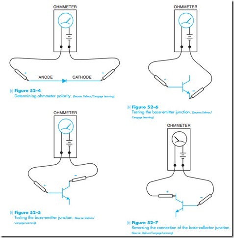
1. Using a diode, determine which ohmmeter lead is positive and which is negative. The ohmmeter will indicate continuity through the diode only when the positive lead is connected to the anode and the negative lead is connected to the cathode, Figure 52–4.
2. If the transistor is an NPN, connect the positive ohmmeter lead to the base and the negative lead to the collector. The ohm- meter should indicate continuity. The reading should be about the same as the reading obtained when the diode was tested, Figure 52–5.
3. With the positive ohmmeter lead still connected to the base of the transistor, connect the negative lead to the emitter. The ohm- meter should again indicate a forward diode junction, Figure 52–6.
NOTE: If the ohmmeter does not indicate continuity between the base-collector or the base-emitter, the transistor is open.
4. Connect the negative ohmmeter lead to the base and the positive lead to the collector. The ohmmeter should indicate infinity or no continuity, Figure 52–7.
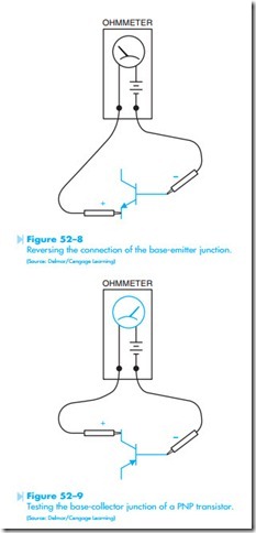
5. With the negative ohmmeter lead connected to the base, reconnect the positive lead to the emitter. There should, again, be no indication of continuity, Figure 52–8.
Reversing the connection of the base-collector junction.
(Source: Delmar/Cengage Learning)
NOTE: If a very high resistance is indicated by the ohmmeter, the transistor is “leaky” but it may still operate in the circuit. If a very low resistance is seen, the transistor is shorted.
6. To test a PNP transistor, reverse the polarity of the ohmmeter leads and repeat the test. When the negative ohmmeter lead is
connected to the base, a forward diode junction should be indicated when the positive lead is connected to the collector or emitter, Figure 52–9.
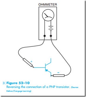
7. If the positive ohmmeter lead is connected to the base of a PNP transistor, no continuity Reversing the connection of a PNP transistor. (Source: Delmar/Cengage Learning) should be indicated when the negative lead is connected to the collector or the emitter, Figure 52–10.


