Electric Baseboard Heaters
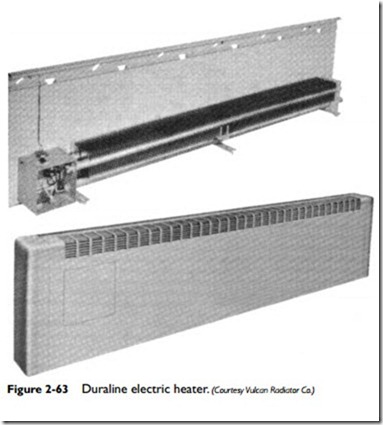
Electric baseboard heaters are designed for use in residential, commercial, industrial, and institutional heating systems. This chapter will be primarily concerned with a description of residential heaters. The electric heaters designed for use in commercial, industrial, or institutional installations differ from the residential type by being larger in capacity; otherwise, they are essentially identical in design (see Figure 2-63).
An electric baseboard heater contains one or more heating elements placed horizontally. Each electric heating element is a unit assembly consisting of a resistor, insulated supports, and terminals for connecting the resistor to the electric power supply.
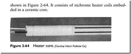
By definition, a resistor is a material used to produce heat by passing an electrical current through it. Solids, liquids, and gases may be used as resistors, but solid resistors are the type most frequently used. Resistors may be made up of wire or metal ribbon, supported by refractory insulation, or embedded in refractory insulating material surrounded by a protective sheath of metal. A typical heating element used in Vulcan electric baseboard heaters is
shown in Figure 2-64. It consists of nichrome heater coils embedded in a ceramic core.
Each resistor is generally rated from 80 to 250 watts (270 to 850 Btu per hour) per linear foot of baseboard unit. The manufacturer will give the ratings for each unit (rather than per linear foot) but will also include its overall length in the data.
Either wall-mounted or built-in thermostats can be used to control the heating elements in electric baseboard heaters. These thermostats (either low-voltage or line voltage types) are designed for single- or multiple-unit control with single- or two-stage heating elements. Normally, multiple-unit control is not feasible with two- stage units or with a built-in thermostat. It is recommended that single-stage heating units be used when it is necessary or desirable to control more than one unit from one thermostat.
Close control of temperatures can be obtained by installing a time-delay relay in the electric baseboard unit. This type of relay is particularly useful when a time delay is needed on switch make or break. Additional information about time-delay relays is included in Chapter 6 of Volume 2 (“Other Automatic Controls”).
A temperature-limit switch (thermal cutout) should be installed in each unit to prevent excessive temperature buildup. The maxi- mum surface temperature for each baseboard enclosure should be limited to 190°F. Exceeding this limit may result in damage to the heater.
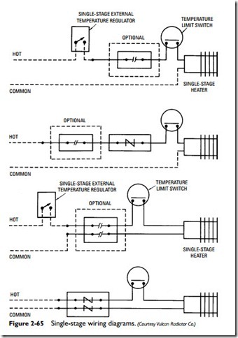
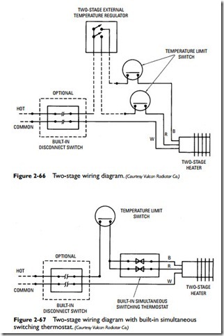
A typical temperature-limit switch used in an electric baseboard installation is the linear capillary type that ensures constant pro- tection over the entire length of the heater. An automatic resetting feature allows the heater to resume operation once conditions return to normal. The temperature-limit switch is usually located between the heater and the thermostat or disconnect switch in the wiring (see Figures 2-65 and 2-66). The only exception occurs when a built-in simultaneous switching thermostat is used (see Figure 2-67).
In a baseboard heating system, each temperature-limit switch must be wired to break the electrical circuit only to the heating element or elements of the unit on which it is installed.


