Convector Piping Connections
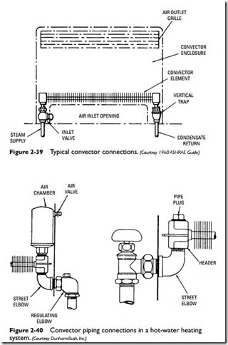
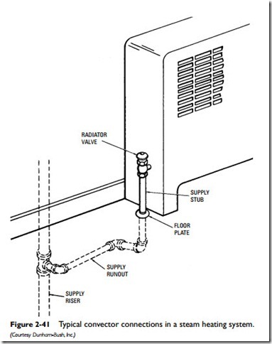
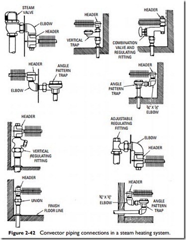
The piping connections for a typical gravity convector are shown in Figure 2-39. Supply connections to the convector heating element are made at the top, bottom, or end of the inlet header. Return connections are made at the bottom or end of the header at the opposite end of the unit. Figure 2-40 illustrates two recommended piping connections for convectors used in a hot-water heating system. Typical convector piping connections for units used in steam heating systems are shown in Figures 2-41 and 2-42.
Gravity convector piping connections are very similar to those used with radiators, except that the lines must be sized for a greater condensation rate. The usual method for determining convector capacities is to convert them to the equivalent square feet of direction radiation (EDR):
The 240 Btu figure represents the amount of heat in Btu given off by ordinary cast-iron radiators per square foot of heating surface per hour under average conditions.
The connections used for a forced hydronic convector are similar to those used with unit heaters (see Unit Heater Piping Connections in this chapter).
Hydronic Fan Convectors
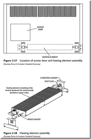
Hydronic system fan convectors are equipped with small fans controlled by a fan switch. The fan blows air across the heating element assembly and into the room or space. If there is no heat, a low-limit aquastat will shut off the fan when the temperature drops below a predetermined setting.


