Gas-Fired Furnaces
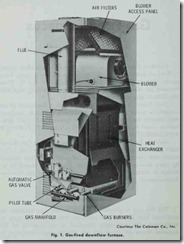
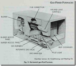
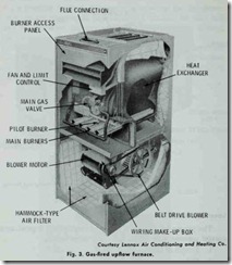
Gas-fired furnaces are available in upflow, downflow (coun terflow), or horizontal flow models for installation in attics, base ments, closet spaces, or at floor level (Figs. 1, 2, and 3). These furnaces are also available in a wide range of heating capacities for different size structures.
This chapter is primarily concerned with a description of the procedures recommended for the installation, operation, servicing, and repair of gas-fired forced warm-air furnaces. Additional infor mation about furnaces is contained in Chapter I 0 (FURNACE FUNDAMENTALS).
Only gas-fired furnaces approved by the American Gas Associ ation should be used in a heating installation. Not only does A.G.A certification insure a certain standard of quality, it is often required by many local codes and regulations. The furnace should be in stalled in accordance with procedures outlined by the N a tiona/ Environmental Systems Contractors Association.
PLANNING SUGGESTIONS
The first step in planning a heating system is to calculate the maximum heat loss for the structure. This should be done in accordance with procedures described in the manuals of the National Warm Air Heating & Air Conditioning Association or by a comparable method. Correctly calculating the maximum heat loss for the structure is very important, because the data will be used to determine the size (capacity) of the furnace selected for the installation.
If the heating or heating /cooling installation is to be approvedby either the FHA or VA, heat loss and heat gain calculations should be made in accordance with the procedure described in 1\/ational Environmental Systems Contractors Manual J.
Locations and Clearances
The proper location of a gas-fired furnace wiii depend upon a careful consideration of the following three factors:
1. Length of heat runs,
2. Chimney location,
3. Clearances.
A gas-fired forced warm-air furnace should be located as near as possible to the center of the heat distribution system and chim ney. Centralizing the furnace reduces the need for one or more long supply ducts which tend to lose a certain amount of heat. The number of elbows should also be kept to a minimum for the same reason. Installing the furnace near the chimney will reduce the length of the horizontal run of flue pipe. The flue pipe should always be kept as short as possible.
Sufficient clearance should be provided for access to the draft hood and flue pipe. It is particular1y important to locate a gas-fired furnace so that the draft hood is at least 6 inches from any com bustible material.
Allowing access for lighting the furnace and servicmg It Is also an important consideration. Most furnace manufacturers rec ommend a clearance of 24 to 30 inches in front of the unit for access to the burner and controls.
Clearances between the furnace and any combustible mater ials are usually provided by the manufacturer in the furnace specifications.
Installation Recommendations
New furnaces for residential installations are shipped preas sembled from the factory with all internal wiring completed. In order to install the new furnace, the gas piping from the supply main, the electrical service from the line voltage main, and the low-voltage thermostat must be connected. Directions for making these connections are to be found in the furnace manufacturer’s installation instructions.
Make certain you have familiarized yourself with all local codes and regulations which govern the installation of a gas-fired furnace. Local codes and regulations take precedence over na tional standards. Your furnace installation must comply with the local codes and regulations.
Always check a new furnace for damages as soon as it arrives from the factory. If shipping damages are found, the carrier (not the factory) should be notified and a claim filed immediately. Heating equipment is shipped FOB from the factory, and it is the responsibility of the carrier to see that it arrives undamaged.
Always place the furnace on a solid level base. This will reduce vibrations from the equipment and keep operating noise to a minimum. In a crawl space installation, the furnace is either sup ported on a slab or on concrete blocks, or it is suspended from floor joists with % inch hanger rods.
A furnace installed in an attic should be placed on a fiber board sheeting base to absorb vibrations. Many furnaces designed for attic installations are certified for installation directly on com bustible material such as ceiling joists or attic floors. ln an attic installation, the furnace should be placed over a load bearing partition for additional support.
Duct Connections
The warm air plenum, warm air duct, and return air duct should be installed in accordance with the recommendations of the National Environmental Systems Contractors Association.
Detailed information about the installation of an air duct sys tem is also contained in the following two publications of the National Fire Protection Association:
1. “Residence Type Warm Air Heating and Air Conditioning Systems” (NFPA No. 90B).
2. “Installation of Air Conditioning and Ventilating Systems of Other than Residence Type” (NFPA No. 90A).
Additional information about duct connections can be found in Chapter 7, Volume 2 (DUCTS AND DUCT SYSTEMS).
It is important for you to remember the following facts about furnace duct connections and the air distribution ducts:
1. Duct lengths should be kept to a minimum by centralizing the furnace location as much as possible.
2. The duct system must be properly sized. Undersizing will cause a higher external static pressure than the one for which the furnace was designed. This may result in a noisy blower or insufficient air distribution.
3. Duct sizing should include an allowance for the future insta1lation of air conditioning equipment.
4. The furnace should be leveled before any duct connections are made.
5. Seal around the base of the furnace with a calking com pound to prevent air leakage if a bottom air return is used.
6. Ducts should be connected to the furnace plenums with tight fittings.
7. Warm air plenum and return air plenum connections should be the same size as the openings on the furnace.
8. Usc tapered fittings or starter collars between the ducts and the furnace plenum.
9. Ductwork located in unconditioned spaces (e.g. unheated attics, basements, crawl spaces etc.) should be insulated if air conditioning is planned for some future date.
10. Install canvas connectors etween air plenums and the casing of the furnace to insure quiet operation. Check local codes and regulations to make certain canvas connectors are in compliance.
11. Line the first 10 feet or so of the supply and return ducts with acoustical material when extremely quiet operation is necessary.
12. Install locking-type dampers in each warm air run to facili tate balancing the system.
Electrical Wiring
All of the electrical wiring inside the furnace is completed and inspected at the factory before the unit is shipped. Wiring instruc tions will accompany each furnace, and the internal (factory in stalled) wiring will be clearly marked. The wiring to controls and to the electrical power supply must be completed by the installer, and the wiring should be done in accordance with the diagram supplied by the manufacturer. This wiring is usually indicated on wiring diagrams by broken lines.
All wiring .connected to the furnace must comply with the National Electric Code and any local codes and regulations. Local codes and regulations will always take precedence over national ones when there is any conflict. In order to validate the furnace warranty, many manufacturers require that a local electrical au thority approve all electrical service and connections.
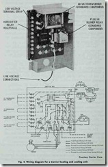
The two types of electrical connections required to field wire a furnace are: (1) line voltage field wiring, and (2) control voltage field wiring. Both of these are shown in the wiring diagram for a Carrier heating/cooling unit (Fig. 4).
The line voltage wiring connects the furnace to the building power supply. It runs directly from the building power panel to a fused disconnect switch. From there, the wiring runs to terminals L1 and L2 on the power supply terminal block (i.e. the furnace junction box).
The unit must be properly grounded either by attaching a ground conduit for the supply conductors or by connecting a separate wire from the furnace ground lug to a suitable ground. The furnace must be electrically grounded in accordance with the National Electric Code (ANSI-C1-1971).
Furnaces equipped with motors in excess of% hp or 12 amps ratings, must be wired to a separate 240 volt service in accordance with the National Electric Code and local codes and regulations. A 240 volt transformer should be installed whenever 240 volt service is required and/or a motor larger than % hp is used.
The external control voltage circuitry consists of the wiring between the thermostat and the low voltage terminal block located in the control voltage section of the furnace. Instructions for control voltage wiring are generally shipped with the thermostat.
Ventilation and Combustion Air
A gas-fired furnace requires an unobstructed supply of air for combustion. This combustion air supply is generally supplied
through natural air infiltration (cracks in the walls and around windows and doors) or through ventilating ducts.
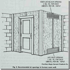
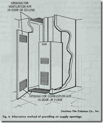
If a gas-fired furnace is located in an open area (basement or utility room) and the ventilation is relatively unrestricted , there should be a sufficient supply of air for combustion and draft hood dilution . On the other hand , if the heating unit is located in an enclosed furnace room or if normal air infiltration is effectively reduced by storm windows or doors, then certain provisions must be made to correct this situation. Fig. 5 illustrates one type of modification that can be made to provide an adequate supply of combustion and ventilation air to a furnace room. As shown, two permanent grilles are installed in the walls of the furnace room, each of a size equal to one square inch of free area per 1000 Btu/hr of burner output. One grille should be located approximately 6 inches from the ceiling, and the other one near the floor. A possible alternative is to provide openings in the door, ceiling, or floor as shown in Fig. 6.
If the furnace is located in a tightly constructed building, it should be directly connected to an outside source of air. A per manently open grille sized for at least one square inch of free area per 5000 Btu per hour of burner output should also be provided. Connection to an outside source of air is also recommended if the building contains a large exhaust fan.
Provisions for ventilation and combustion air are described in greater detail in “Installation of Gas Appliances and Gas Piping” (ASA Z21.30-NFPA No. 54). These standards were adopted and approved by the National Fire Protection Association and the National Board of Fire Underwriters.
Venting
Provisions must be made for venting the products of combus tion to the outside in order to avoid contamination of the air in the living or working spaces of the structure. The four basic meth ods of venting the products of combustion to the outside are:
1. Masonry chimneys,
2. Low heat Type A prefabricated chimneys,
3. Type B gas vents,
4. Type C vents,
5. Wall venting.
Masonry and prefabricated chimneys are described below (see CHIMNEYS and TROUBLESHOOTING CHIMNEYS).
Low heat Type A flues are metal, prefabricated chimneys that have been tested and approved by the Underwriters’ Laboratories. These chimneys are easier to install than masonry chimneys , and are generally safer under abnormal firing conditions.
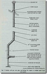
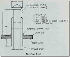
Type B gas vents (Fig. 7) are listed by the Underwriters‘ Laboratories, and are recommended for venting all standard gas-fired furnaces. They are not recommended for incinerators, combination gas-oil appliances, or appliances convertible to solid fuel. Check the furnace specifications for the type of vent to use. It will usually be A.G.A. certified for use with a Type B gas vent. A Type C vent is used to vent gas-fired furnaces in attic installations (Fig. 8).
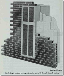
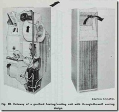
Wall venting involves gas-fired appliances which have their combustion process, combustion air supply, and combustion prod ucts isolated from the space which is being heated. These appli ances are generally vented through the wall (Figs. 9 and 10).
Flue Pipe
The flue is the general term used to describe the passage through which the flue gases pass from the combustion chamber of the furnace (or boiler) to the outside. A flue is also referred to as a flue pipe, vent pipe, or vent connector.
The term appliance flue refers to the flue passages inside a furnace or boiler. A chimney flue is the vertical flue passage run ning up through the chimney. A vent connector is specifically the flue passage between the heating unit and the chimney. It is also variously referred to as a chimney connector or smoke pipe. A flue outlet or vent is the opening in a furnace or boiler through which the flue gases pass.
The flue pipe (vent pipe) connects the smoke outlet of the furnace with the chimney. It should never extend beyond the inner liner of the chimney, and should never be connected to the flue of an open fireplace. Furthermore, flue connections from two or more sources should never enter the chimney at the same level from opposing sides.
The horizontal run of flue pipe should be pitched toward the chimney with a rise of at least inch per running foot. Some furnace manufacturers recommend as much as a 1 inch minimum rise per running foot. Do not allow the horizontal run to exceed, in length, 75% of the vertical run. Vent pipe crossovers in an attic must not extend at an angle of less than 60° from the vertical.
At intervals, fasten the horizontal run of flue pipe securely with sheet metal screws and support the pipe with straps or hangers to prevent sagging. Sagging can cause cracks to develop at the joints which may result in releasing toxic flue gases into the living and working spaces of the structure.
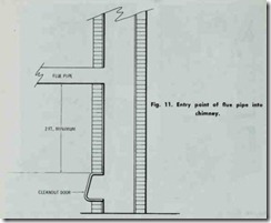
The point at which the flue pipe enters the chimney should be at least two feet above the clean out opening of the chimney (Fig. 11). The flue pipe must be the same size as the outlet of the flue collector (furnace flue collar). Never install a damper in a flue pipe or reduce the size of the flue pipe. Run the flue pipe from the draft hood to the chimney in as short a distance as possible. All joints in the flue pipe should be made with the length nearest the furnace overlapping the other.
If excessive condensation is encountered, install a drip tee in place of an elbow. Never use dampers or other types of restrictors in the vent pipe. A minimum distance should be maintained be tween the vent pipe and the nearest combustible material.
When more than one appliance is vented into a common flue, the area of the common flue should be equal to the area of the largest flue plus 50% of the area of the additional flue
