VENTILATION REQUIREMENTS
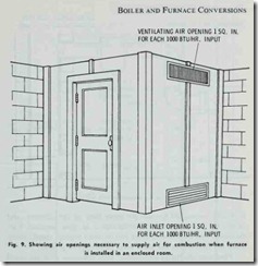
If the existing boiler or furnace is located in an open area (basement or utility area) and the ventilation is relatively unre stricted, there should be a sufficient supply of air for combustion and draft hood dilution. On the other hand, if the heating unit is located in an enclosed furnace room or normal air infiltration is effectively reduced by storm windows or doors, then certain pro visions must be made to correct this situation. Fig. 9 illustrates the type of modification that should be made in a furnace room to provide an adequate supply of air. As shown, two permanent grilles are installed in the walls of the furnace room, each of a size equal to one square inch of free area per 1000 Btu per hour of burner output. One grille should be located near the ceiling, and the other near the floor.
If the boiler or furnace is located in an area of particularly tight construction, the heating unit should be directly connected to an outdoors source of air. A permanently open grille sized for grilles are installed in the walls of the furnace room, each of a size equal to one square inch of free area per 1000 Btu per hour of burner output. One grille should be located near the ceiling, and the other near the floor.
If the boiler or furnace is located in an area of particularly tight construction, the heating unit should be directly connected to an outdoors source of air. A permanently open grille sized for It should not extend beyond the inner liner of the chimney, and should never be connected with the flue of an open fireplace. Fur thermore, flue connections from two or more sources should never enter the chimney at the same level from opposing sides.
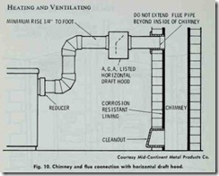
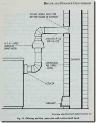
Flue pipe should be constructed from corrosive resistant metal and be designed with as few sharp turns as practical. The straight est and shortest possible passage should be provided for the exist ing flue gases.
Pitch the flue pipe with a rise toward the chimney of at least Y4 inch per foot. At approximate intervals, fasten the flue pipe securely with sheet metal screws to prevent sagging.
Masonry is recommended for the construction of chimneys (pre-fab chimneys are also found suitable). Outside metal stacks are generally found unsuitable for oil-fired burners.
The ordinary chimney must be at least 3 feet higher than the roof or 2 feet higher than any ridge within 10 feet of the building in order to avoid down drafts.
Aside from adapting the furnace or boiler for a conversion burner, changes must also be made in the passages formed by the heating surface.
Extra large flue passages are not suited to the high temperature flue gas encountered with oil. In boilers having these large flue passages, batHing must be resorted to in order to slow down the high velocities of the extra hot gases, otherwise unburned particles of oil may lodge on the heating surface, resulting in carbon. Be cause carbon is an excellent insulator, the efficiency of the heating surface is lowered whenever it collects. See BAFFLING in this chapter.
BAFFLING
Baffling is a type of obstruction designed to deflect and regulate the speed of flue gases. They are especially necessary for round boilers and furnaces constructed so that the flue passes are almost direct from the fire box. Furthermore, boilers designed for burning coal are usually provided with relatively large flue passages which are not normally suited to the higher flue gas velocities encountered in oil firing.
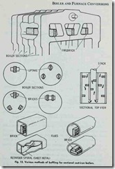
Baffling will, in most cases, help to partly overcome the in efficient operation resulting from the usual excessively high stack gas temperatures. In such instances it is advisable to experiment with various methods of baffling as shown in Fig. 12. Note: any baffling of the flue passes of a nature which prevents efficient operation of the burner should not be done.
Another form of baffling is a corbel or step out arrangement of the brick work of the rear wall, forming a target wall which the flame strikes and is curled back to prevent short circuiting.
GAS PIPING AND PIPING CONNECTIONS
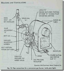
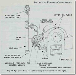
Figs. 13 and 14 illustrate the piping connections necessary for two different m odels of gas-fired conversion burners. Always refer to local installation codes for guidance, because your piping must comply with these codes. Other helpful sources of information are the following booklets from the American Gas Association:
I. Bulletin Z21.30, “Installation of Gas Appliances and Gas Piping.”
2. Bulletin Z21.8, “Installation of Domestic Gas Conversion Burners.”
Also helpful is NFPA Bulletin No. 54, “Gas Appliances and Gas Piping,” which is available from the National Fire Protection Association.
No matter what type of gas-fired conversion burner you decide to use , it must be allowed to develop its rated capacity. This can be accomplished by making certain the burner is connected to a gas supply containing sufficient pressure.
In addition to providing for a gas supply with sufficient pres sure, the following recommendations are also offered:
1. Provide for a separate gas supply line of 1 inch pipe size direct from the meter to the burner (ample for runs up to 60 feet in length).
2. Install an intermediate regulator if the line pressure ex ceeds 13.5 inch W.C.
3. Connect the burner to the piping as shown in Figs. 13 and 14.
4. Install a manually operated main shut-off valve 4 to 5 feet above the floor on the vertical pipe.
5. Make certain the pipe is clean and free of any scale.
6. Use malleable iron fittings.
7. Remove all burrs and scales from the pipe and clean it before installing it.
8. Do not tap off from the bottom of horizontal runs when branching from a pipe line.
GAS INPUT SETTING
The gas-fired conversion burner illustrated in Fig. 13 is manu factured to operate on natural gas, but kits are available for con verting to propane. A very important factor to be considered when installing these burners is a correct determination of the gas input setting, which should be based on the following two factors:
1. The heating rate of the structure.
2. The rated maximum input of the burner.
The heating rate of a structure is essentially the cmount of warm air that the heating unit must deliver in order to adequately heat it. Methods for calculating the amount of heat required (i.e. the heating rate) were described in Chapter 4 (HEP_TING CALCULATIONS).
Another important factor to consider is the rated maximum input of the burner. The gas input cannot exceed this r’!ting. If the burner maximum input of the burner is below the required minimum of heat indicated by the heating rate, then the burner is inadequate for your needs.
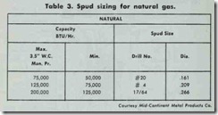
The gas input setting for a natural gas conversion burner is regulated by the spud sizing and the pressure regulator. A burner is commonly shipped with three different spud sizes, one for each of three capacity range (high, intermediate, and low. Table 3). The capacity range is changed by using a different spud sizing. After the appropriate spud has been installed, the final gas input setting is made by adjusting the pressure regulator. Be sure to carefully read the burner manufacturer’s installation instructions.
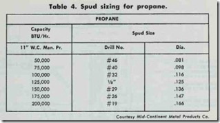
A propane gas conversion burner operates directly on 11″w.c. gas supply pressure as determined by the propane tank reg ulator. The portion of the combination control on the standard natural gas burner is blanked off with a plate provided in the pro pane conversion kit. Two spuds are provided: a minimum sized main spud and a pilot spud. The main spud must be redrilled for the required capacity (see Table 4).
INSTALLING A CONVERSION GAS BURNER
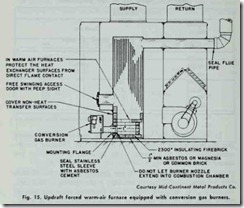
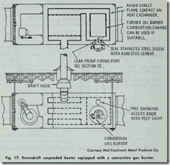
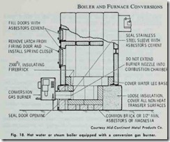
The conversion gas burners illustrated in Figs. 13 and 14 are used to convert coal-fired or oil-fired central heating plants to gas. They are adaptable for use in forced warm-air furnaces, gravity (updraft) furnaces, or boilers (Figs. 15, 16, 17 and 18).
In addition to the basic combustion chamber requirements (see the appropriate section in this chapter), the following recom mendations must be followed when installing a conversion gas burner.
1. The diameter of the burner opening into the combustion chamber must not be oversize. If the opening is oversized, slip the stainless steel sleeve (included with the burner) over the nozzle and fill in the remaining space with refrac tory cement.
2. Position the end of the burner nozzle so that it is at least 1 inch short of the inside surface of the combustion cham ber. Never allow the nozzle to extend into the combustion chamber.
3. If the burner nozzle is too short to reach the combustion chamber, it may be lengthened with an extension tube.
4. Check the burner ports and pilot before permanently set ting the burner in place, and remove any foreign matter blocking the openings.
