INSTALLING GAS PIPING
The principal recommendations to be followed when installing gas piping are:
1. A single gas line must be provided from the main gas sup ply to the furnace.
2. The gas supply pipe must be sized according to the volume of gas used and the allowable pressure drop.
3. The supply riser and drop leg must be installed adjacent to the furnace on either side. Never install it in front of the furnace where it might block access to the unit.
4. A manual main shutoff valve or plugcock should be in stalled on the gas supply piping (usually on the riser) out side the unit in accordance with local codes and regulations.
5. Install a tee for the drop leg in the pipe at the same level as the gas supply (inlet) connection on the furnace.
6. Extend the drip leg and cap it.
7. Install a ground union joint between the tee and the furnace controls.
8. Use a pipe compound resistant to LP gas on all threaded pipe connections in an LP gas installation.
9. Test for pressure and leaks. Use a solution of soap or de tergent and water to detect any leaks. Never check for leaks with a flame.
START UP INSTRUCTIONS
The start up procedure for most gas-fired furnaces is very simi lar, particularly insofar as use of the thermostat is concerned. The major difference is in the lighting of the pilot burner, and this will depend upon the type of gas valve used.
The start up procedure for a gas-fired furnace may be summar ized as follows:
1. Open all warm air registers.
2. Shut off main gas valve and pilot gas cock, and wait at least 5 minutes to allow gas which may have accumulated in the burner compartment to escape.
3. Set the room thermostat at the lowest setting.
4. Open the water supply valve if a humidifier is installed in the system.
5. Turn off the line voltage switch if one is provided in the furnace circuit.
6. Light the pilot (see below).
7. Turn electrical power on.
8. Replace all access doors.
9. Light main burners by setting the room thermostat above the room temperature.
10. Set the room thermostat at the desired temperature after the main burners are lighted.
Lighting The Pilot
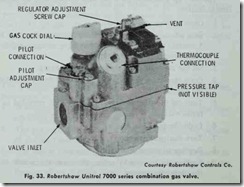
The pilot lighting instructions should be included with the fur nace and prominently displayed. Lighting instructions for the 24 volt Honeywell V8280, V8243, and Robertshaw (Unitrol) 7000 combination gas valves basically summarize the pilot lighting pro cedure (Fig. 33). The procedure is as follows:
1. Depress gas cock dial and tum it counterclockwise to “pi lot” position.
2. Keep gas cock dial depressed and light pilot with a match.
3. Keep dial depressed until pilot remains lighted when released.
4. Depress dial and turn counterclockwise to “on” position.
BLOWERS AND MOTORS
A forced warm-air furnace should be equipped with a variable speed electrical motor designed for continuous duty. The motor should be provided with overcurrent protection in accordance with the National Electrical Code (ANSI C1-1971).
Blower motors are available as either direct-drive or belt-driven units. On direct-drive units, the blower wheel is mounted directly on the motor shaft and runs at motor speed. The blower wheel of a belt-driven unit is operated by a V-belt connecting a fixed pulley mounted on the blower shaft with a variable pitch drive pulley mounted on the motor shaft.
The blower motors used in residential furnaces are single-phase electrical motors. Depending upon the method used for starting, they may be classified as:
1. shaded pole,
2. permanent split capacitor,
3. split-phase,
4. capacitor-start motors.
A direct-drive blower generally uses a shaded pole (SHP) or permanent capacitor (PSC) type motor. Belt-driven blower motors are usually split-phase (SPH) types up to the Y3 hp size. Larger motors are capacitor-start split-phase motors.
Blower motors are fractional horsepower motors commonly available in the following sizes: Yt 2 , Yt.0, %, ‘ Y3, Y2, and horsepower. A fractional horsepower motor should be protected
with temperature or current-sensitive devices to prevent motor winding temperatures from exceeding those allowed in the speci fications.
Provisions should be made for the periodic lubrication of the blower and motor. Use only the type and grade of lubricant speci fied in the operating instructions. Do not over lubricate. Too much oil can be just as bad as too little. A direct-drive blower should be capable of operating within the range of air temperature at the static pressures for which the furnace is designed and at the voltage specified on the motor name plate.
Motors using belt drives must be supplied with adjustable pul leys. The only exception is a condenser motor used on a forced warm-air furnace with a cooling unit. A !ways provide the means for adjusting a belt-driven motor in an easily accessible location.
Most forced warm-air furnaces are shipped with the blower motors factory adjusted to drive the blower wheel at a correct speed for heating. This is a slower speed than the one used for air conditioning, but it is relatively easy to alter the air delivery to meet the requirements of the installation see AIR CONDITIONING in this chapter).
Air Delivery and Blower Adiustment
The furnace blower is used to force air through the heat ex changer in order to remove the heat produced by the burners. This removal of heat by the blower serves a twofold purpose: it distrib utes the heat through the supply ducts to the various spaces in the structure, and (2) it protects the surfaces of the heat exchanger from overheating.
Most blowers are factory set to operate with a specific air tem perature rise. For example, Janitrol Series 37 gas-fired furnaces are certified by the American Gas Association to operate within a range of 70°-l00 °F air temperature heat rise. In other words, the temperature of the air within the supply ducts may be 70°-l00°F higher than the air temperature in the return duct. A temperature rise of 85°-90°F with approximately 0.1 inch external pressure in the area beyond the unit and filter is generally considered adequate for most residential applications.
The furnace air delivery rate should be adjusted at the time of installation to obtain a temperature rise within the range speci fied on the furnace rating plate. Many furnace manufacturers rec ommend that the temperature rise be set below the maximum to insure that temperature rise will not exceed maximum requirement should the filter become excessively dirty.
Although the blower and motor are factory set to operate within a specific temperature rise range, the unit can be field adjusted to deliver more or less air as required. The air delivery rate is ad justed by changing the blower speed. On direct-drive motors, this is accomplished by moving the line lead to the desired termi nal. Belt-driven motors are adjusted by changin the effective di ameter of the driver pulley. (see below: DIRECT DRIVE BLOWER ADJUSTMENT and BELT DRIVE BLOWER AD JUSTMENT).
Direct Drive Blower Adiustment
The blower (fan) of a direct drive unit is operated by a drive shaft connected to the motor. Three common types of direct drive motors used with blowers are:
1. Two speed direct drive shaded pole motor.
2. Three speed direct drive PSC motor.
3. Four speed direct drive PSC motor.
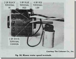
These blower motors are shipped from the factory set for low speed heating operation. If a higher operating speed is desired, the red blower motor wire must be moved from the low speed red terminal to a higher speed terminal (Fig. 34).
Belt Drive Blower Adiustment
Air temperature rise can be decreased by increasing the blower speed. A belt drive unit can be adjusted for a higher speed as follows:
1. Loosen the set screw in the movable outer flange of the motor pulley.
2. Reduce the distance between the fixed flange and the mov able flange of the pulley.
3. Tighten the set screw.
The procedure for decreasing the blower speed (and thereby increasing the air temperature rise) is similar except that in Step 2 above the distance between the fixed flange and the movable flange of the pulley are increased.
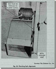
The motor and blower pulley should be aligned to minimize belt wear. The belt should be parallel to the blower scroll, as shown in Fig. 35. Adjustments can be made by moving the motor or adjusting the pulley on the shaft.
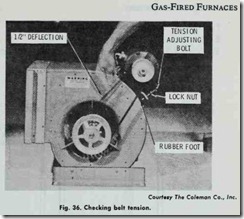
Correct belt tension is also important. Belt slippage occurs when there is too little tension. Too much tension will cause motor overload and bearing wear. Correct belt tension will usually be in dicated by the amount of depression in the belt midway between the blower and motor pulleys. Usually this will be a 1 inch depres sion at the center of the belt. On the Coleman belt driven unit shown in Fig. 36 it is only lh inch.


