AIR FILTERS
A forced warm-air gas-fired furnace is supplied with either a disposable air filter or a permanent (washable) one. The type of filter will be indicated on a label attached to the filter. Never use a filter with a gravity warm-air furnace, because it will obstruct the air flow.
Proper maintenance of the air filter is very important to the operating efficiency of the furnace. A dirty, clogged air filter re duces the air flow through the furnace and causes air temperatures inside the unit to rise. This increase in air temperature results in a reduced life for the heat exchanger and a lower operating efficiency for the furnace.
If a disposable air filter is used, it should be inspected on a monthly basis. If it is dirty, it should be replaced. This is usually done at the beginning and middle of the heating season. The same schedule should be followed during the summer months when air conditioning is used.
If a permanent filter is provided, it must be removed and cleaned from time to time. Cleaning the filter involves the follow ing procedure:
1. Shake it to remove dust and dirt particles.
2. Vacuum it.
3. Wash it in a solution of soap or detergent and water.
4. Allow time for it to dry.
5. Replace it in the furnace.
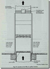
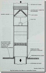
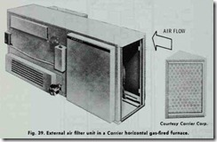
Read the label on the filter for any special instructions that may apply to cleaning it. The location of filters in upflow and counter-flow furnaces is shown in Figs. 37 and 38. Note that in each case the air filter is placed directly in the path of the air enter ing the furnace. An external filter unit for a horizontal gas-fired furnace is shown in Fig. 39.
A filter should be installed in the return plenum or duct when air conditioning is added to the system. Because air conditioning normally requires a greater volume of air than heating, the filter should be sized for air conditioning rather than heating.
Access to internally installed filters is generally provided through a service panel on the furnace. Instructions for cleaning or replacing the filters should be placed on the service panel. It would be a good idea to include the dimensions of the replacement filter(s) in the information.
An adequate filter should provide at least 50 square inches of area per 100 cfm of air circulated. For an air velocity of 1000 cfm, this would mean a filter area of 400 square inches. Filters sized on 50 square inches for each 100 cfm meet the requirements of air conditioning, which requires a greater volume of air than heating.
Never use a smaller size filter than the one required in the spec ifications. To do so would create excessive pressure drop at the filter which would reduce the operating efficiency of the furnace.
Additional information about air filters can be found in Chap ter 14, Volume 3 (AIR CLEANERS AND FILTERS).
AIR CONDITIONING
If you intend to install air conditioning equipment at some fu ture date, the duct sizing should include an allowance for it. Air conditioning involves a greater volume of air than heating. Quite often the blowers and motors of the furnace will be sized for the addition of cooling with matching evaporator coil and condensing unit. Check the specifications to be sure.
All ductwork located in unconditioned areas (e.g. attics, crawlspaces, etc.) downstream from the furnace should be insulated. A furnace used in conjunction with a cooling unit should be installed in parallel or on the upstream side of the evaporator coil to avoid condensation on the heating element. In a parallel installation , dampers or comparable means should be provided to prevent chilled air from entering the furnace.
INSTALLATION AND MAINTENANCE CHECK LIST
A properly installed and maintained furnace will operate effi ciently and economically. The following installation check list is offered as a guide for the installer.
1. Adjust primary air shutter.
2. Provide sufficient space for service accessibility.
3. Check all field wiring.
4. Supply line fuse or circuit breaker must be of proper size and type for furnace protection.
5. Line voltage must meet specifications while furnace is operating.
6. Air flow must be sufficient.
7. Ventilation and combustion air must be sufficient.
8. Duct work must be checked for proper balance, velocity, and quietness.
9. Measure the manifold pressure.
10. Check all gas piping connections for gas leaks (USE SOAP AND WATER NOT A FLAME).
11. Cycle the burners.
12. Check limit switch.
13. Check fan switch.
14. Adjust blower motor for desired speed.
15. Make sure air filter is properly secured.
16. Make sure all access panels have been secured.
17. Pitch air conditioning equipment condensation lines to wards a drain.
18. Check thermostat heat anticipator setting.
19. Check thermostat for normal operation.
20. Clear and clean the area around the furnace.
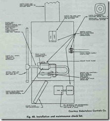
A general check list for both furnace installation and main tenance is shown in Fig. 40. Other maintenance recommendations are contained in various sections of this chapter.
TROUBLESHOOTING A GAS-FIRED FURNACE
The list that follows contains the most common operating prob lems associated with gas-fired furnaces. Each problem is given in the form of a symptom, the possible cause, and a suggested rem edy. This list is intended to provide the operator with a quick ref erence to the cause and correction of a specific problem.
| Symptom and Possible Cause | Possible Remedy |
| Flame Too Large | |
| (a) Pressure regulator set too | (a) Reset using manometer high |
| (b) Defective regulator | (b) Replace |
| (c) Burner orifice too large | (c) Replace with correct size |
| Noisy Flame | |
| (a) Too much primary air | (a) Adjust air shutters |
| (b) Noisy pilot | (b) Reduce pilot gas |
| (c) Burr in orifice | (c) Remove burr or replace orifice |
| Yellow Tip Flame | |
| (a) Too little primary air | (a) Adjust air shutters |
| (b) Clogged burner ports | (b) Clean ports |
| (c) Misaligned orifices | (c) Realign |
| (d) Clogged draft hood | (d) Clean |
| Floating Flame | |
| (a) Blocked venting | (a) Clean |
| (b) Insufficient primary air | (b) Increase primary air supply |
| Delayed Ignition | |
| (a) Improper pilot location | (a) Reposition pilot |
|
(b) Pilot flame too small |
(b) Check orifice, clean, increase pilot gas |
| (c) Burner ports clogged near | (c) Clean ports pilot |
| (d) Low pressure | (d) Adjust pressure regulator |
| Failure to Ignite | |
| (a) Main gas supply off | (a) Open manual valve |
| (b) Burned out fuse | (b) Replace |
| (c) Limit switch defective | (c) Replace |
| (d) Poor electrical connections | (d) Check, clean and tighten |
| (e) Defective gas valve | (e) Replace |
| (f) Defective thermostat | (f) Replace |
| Burner Will Not Tum Off | |
| (a) Poor thermostat location | (a) Relocate |
| (b) Defective thermostat | (b) Check calibration. Check switch and contacts. Replace. |
| (c) Limit switch maladjusted | (c) Replace |
| (d) Short circuit | (d) Check operation a valve. Check for short and correct. |
| (e) Defective or sticking | (e) Clean or replace automatic valve |
| Rapid Burner Cycling | |
| (a) Clogged filters | (a) Clean or replace |
| (b) Excessive anticipation | (b) Adjust thermostat anticipator for longer cycles |
| (c) Limit setting too low | (c) Readjust or replace limit |
| (d) Poor thermostat location | (d) Relocate |
| Rapid Fan Cycling | |
| (a) Fan switch differential | (a) Readjust or replace too low |
| (b) Blower speed too high | (b) Readjust to lower speed |
| Blower Will Not Stop | |
| (a) Manual fan ON | (a) Switch to automatic |
| (b) Fan switch defective | (b) Replace |
| (c) Shorts | (c) Check wiring and correct |
| Noisy Blower and Motor | |
| (a) Fan blades loose | (a) Replace or tighten |
|
(b) Belt tension improper |
(b) Readjust (usually allow 1 inch slack) |
| (c) Pulleys out of alignment | (c) Realign |
| (d) Bearings dry | (d) Lubricate |
| (e) Defective belt | (e) Replace |
| (f) Belt rubbing | (f) Reposition |
| Burner Will Not Tum On | |
| (a) Pilot flame too large or | (a) Readjust too small |
| (b) Dirt in pilot orifice | (b) Clean |
| (c) Too much draft | (c) Shield pilot |
| (d) Defective automatic | (d) Replace pilot valve |
| (e) Defective thermocouple | (e) Replace |
| (f) Improper thermocouple | (f) Properly position position thermopile |
| (g) Defective wiring | (g) Check connections, tighten and repair shorts |
|
(h) Defective thermostat |
(h) Check for switch closure and repair or replace |
| (i) Defective automatic valve | (i) Replace |
| Blower Will Not Run | |
| (a) Power not on | (a) Check power switch. Check fuses and replace if necessary |
| (b) Fan control adjustment | (b) Readjust or replace too high |
| (c) Loose wiring | (c) Check and tighten |
| (d) Defective motor overload, | (d) Replace motor protector, or motor |
| Not Enough Heat | |
| (a) Thermostat set too low | (a) Raise setting |
| (b) Lamp or some other heat | (b) Move heat source away source too close to from thermostat thermostat |
| (c) Thermostat improperly | (c) Relocate thermostat located |
| (d) Dirty air filter | (d) Clean or replace |
| (e) Thermostat out of | (e) Recalibrate or replace calibration |
| (f) Limit set too low | (f) Reset or replace |
| (g) Fan speed too low | (g) Check motor and fan belt and tighten if too loose |
| Too Much Heat | |
| (a) Thermostat set too high | (a) Lower setting |
| (b) Thermostat out of | (b) Recalibrate or replace calibration |
| (c) Short in wiring | (c) Locate and correct |
| (d) Valve sticks open | (d) Replace valve |
| (e) Thermostat in draft or | (e) Relocate thermostat to on cold wall sense average temperature |
|
(f) By-pass open |
(f) Close by-pass |


