Coal-Fired Furnaces
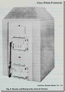
Coal-fired furnaces burn coal or coke. Some are designed to burn coal in combination with one or more other types of fuels such as gas, oil, and/or wood (see MULTI-FUEL FURNACES in this chapter). Both gravity and forced warm-air furnaces are available for use with solid fuels (Figs. 1 and 2).
Coal furnaces are either hand fired or fired with a coal stoker.
A stoker is an automatic coal feeding device that carries the coal from the storage bin to the furnace as needed.
The fire in a coal furnace must be kept burning throughout the heating season. The fire must be attended at regular intervals. The supply of fuel, method of feeding and regulation is always based on weather conditions.
Solid fuel forced warm-air furnaces are rated in accordance with equations provided by the National Warm Air Heating and Air Conditioning Association. Check the latest edition of their publication “Commercial Standard for Solid-Fuel-Burning Forced Air Furnaces.”
PLANNING SUGGESTIONS
The first step in planning a heating system is to calculate the maximum heat loss for the structure. This should be done in accordance with procedures described in the manuals of the Na tiona[ Warm Air Heating and Air Conditioning Association or by a comparable method. This is very important because the data will be used to determine the size (capacity) of the furnace selected for the installation.
Location and Clearance
A coal-fired furnace should be located a safe distance from any combustible materials. Consult the local codes and regulations for the required clearances.
Never obstruct the front of the furnace. Access must be pro vided to the fire and ashpit doors in order to operate the furnace.
A centralized location for the furnace usually results in the best operating characteristics, because long supply ducts and the heat loss associated with them are eliminated.
Installation Recommendations
Make certain you have familiarized yourself with all local codes and regulations which govern the installation of coal-fired furnaces and coal stokers. Local codes and regulations take precedence over national standards.
Coal-fired furnaces are shipped disassembled with complete assembly instructions. The installer must assemble the furnace in accordance with these instructions. If the furnace is fired by a coal stoker or contains some automatic controls, the installer must connect the electrical service from the line voltage main. The low voltage thermostat must also be connected.
Duct Connections
Detailed information concerning th_e installation of an air duct system is contained in the following two publications of The Na tional Fire Protection Association:
1. “Installation of Air Conditioning and Ventilating Systems of Other Than Residence Type” (NFPA No. 90A).
2. “Residence Type Warm Air Heating and Air Conditioning Systems” (NFPA No. 90B).
Additional information about duct connections can be found in Chapter 7, Volume 2 (DUCTS AND DUCT SYSTEMS). The comments in Chapter 11 (GAS-FIRED FURNACES) about fur nace duct connections and air distribution ducts also apply to ducts used with coal-fired forced warm-air furnaces.
Electrical Wiring
A wiring diagram specifying the electrical connections between th e various controls should be sent by the stoker manufacturer.
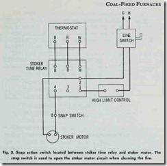
As shown in Fig. 3, a room thermostat operating through the stoker tim e relay starts and stops the stoker in response to temperature conditions. The time relay operates the stoker to keep the fire alive during periods when heat may not be required by the room thermostat. A stoker time relay should include a device to shut down the stoker immediately after a shut down call from the thermostat. This action eliminates fuel waste by preventing the overshootin of room temperature.
A high limit control is used to protect the system against excessive temperatures. This control takes the form of an air switch in a warm air heating system.
A snap switch should be installed in the wiring between the stoker time relay and the stoker motor to open the stoker motor circuit when the fire is being cleaned (Fig. 3).
A wiring diagram for a combination wood-oil furnace is shown in Fig. 4. Note that the wood controls and oil controls are wired as separate systems. This is a common practice on furnaces de signed to bum more than one fuel.
Ventilation and Combustion Air The total draft requirement of a coal-fired furnace is greater than those which burn gas or oil, because the chimney draft must overcome the resistance of the fuel bed.
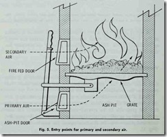
Both a primary and secondary air supply are necessary for the combustion of solid fuels. The primary air passes through the fuel bed generally on an upward path from the ashpit. The sec ondary air is usually admitted through slots in the furnace fire door and passes over the fire to complete the combustion process (Fig. 5).
On residential type furnaces, the secondary air slots in the fire door should be kept closed. There is usually enough air leak age to admit a suitable amount of secondary air without having to open the fire door. An excessive amount of secondary air (par ticularly after the fire has taken hold) will actually reduce the efficiency of the furnace.
The draft will determine the rate at which the fuel is burned. The draft in furnaces using coal or coke will depend upon the following factors:
1. Type of fuel (anthracite or bituminous; coke, etc.).
2. Size of fuel.
3. Fuel bed thickness.
4. Ash and clinker accumulation.
5. Flue resistance to the flow of gas.
6. Soot accumulation in flue.
7. Grate area.
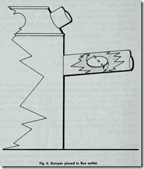
The rate at which the fuel is burned will depend upon the heating load demand of the specific location. The burning rate can be varied by reg!.Ilating the draft. One of the most effective methods of doing this is by placing a damper in the flue outlet (Fig. 6). This method proportionally reduces both primary and secondary air.
The use of an ashpit damper is required for low combustion rates. A cold air check damper is necessary when there is excessive chimney draft.
Venting
Provisions must be made for venting the products of combus tion to the outside in order to avoid contamination of the air in the living or working spaces of the structure. Masonry chimneys and low heat Type A prefabricated chimneys are the most common methods of venting coal-fired furnaces.
Flue Pipe
Coal-fired furnaces require flue passages that are larger than those used with other types of fuels. This is due to the far greater volume of smoke, soot and other products of combustion associated with burning solid fuels.


