VACUUM RELIEF VALVES
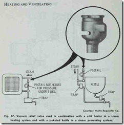
A vacuum relief valve (Fig. 47) is an effective means of pro viding protection against the build up of excessive vacuum conditions in steam heating and steam processing systems. They are also used in combination with temperature-pressure relief valves on water heaters.
Vacuum conditions can often occur after the supply line has been shut off. Steam condenses and a vacuum can be created which not only affects system operation but can also cause dam age to equipment. The vacuum relief valve automatically admits air to the system in order to break up the vacuum. These valves operate under conditions up to a maximum temperature of 250°F. The valve disc should be constructed from a material capable of withstanding high temperatures, particularly when the valve is used in a steam processing system.
STEAM BOILER INJECTORS
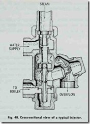
A steam boiler injector is a device used on some boilers to cre ate accelerated steam circulation in a steam heating system. The essential parts of a boiler injector are shown in Fig. 48.
This device operates on the induction principle. In operation, steam from the boiler, entering the steam nozzle, passes through it, through the space between the steam nozzle and combining tube, and then out through the overflow. This produces a vacuum which draws in the water through the water inlet. The incoming cold water condenses the steam in traversing the combining tube, and the water jet thus formed is driven at first out through the overflow. As the velocity of the water jet increases, sufficient mo mentum is obtained to overcome the boiler pressure, with the re sult that the water enters the delivery tube and passes the main check valve into the boiler.
The induction principle of the steam injector is the same as the operating principle of hydraulic boosters used in forced hotwater heating systems with the exception that fast flowing hot water is used instead of steam to obtain the inductive action to accomplish accelerated circulation.
TRY COCKS
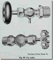
Try cocks are small valves installed on steam boilers at the safe high-water level and at the safe low-water level (Fig. 49). When the boiler water column is inoperable, try cocks function as a back up system to determine the water level. The water level is determined by opening slightly first one try cock and then the other. The water level is indicated by the color of the plume escap ing from the try cock orifice. A steam plume is characteristically colorless, and will indicate that the water level is too low (i.e. be low the level of the try cock orifice). Water, on the other hand, is characterized by a white plume. A false water level reading will be obtained if the try cock is opened too wide when the level of the water is only slightly below the level of the try cock orifice. The violent agitation of the water caused by a wide open try cock will result in some of the water escaping, giving the false impres sion that the level of the water in boiler is at or above the try cock fitting.
On large steam boilers, a third try cock is often installed be tween the other two. Sometimes a try cock on these larger boilers is at a level too high to reach. When this is the case, chain opera ed lever-type try cocks are installed.
BLOW-OFF VALVE
Sediments, contaminants and other impurities found in water will settle out over a period of time and accumulate at a low point in the bottom of the boiler. These can be removed by means of a blow-off valve placed in a line connected to the lowest part of the boiler. The blow-off valve is opened periodically and the accumu lated sediments are drained off.
FUSIBLE PLUGS
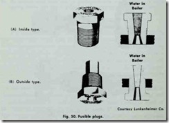
A fusible plug is used on some boilers as a protection against dangerous low water conditions. Examples of fusible plugs are shown in Fig. 50. They are generally made of bronze and filled
with pure tin. When the temperature (and pressure) in the boiler builds up to about 450 °F (the approximate melting point of pure tin), the tin core melts and relieves the pressure within the boiler.
Fusible plugs must comply with ASME standards, and are available in several sizes for use on boilers having a steam pres sure of less than 250 psi.
STEAM LOOP
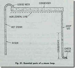
A steam loop (Fig. 51) is a piping arrangement used in a steam heating system to return condensation to the boiler. The principal components of a steam loop piping arrangement are:
1. Riser,
2. Condenser,
3. Drop leg,
4. Check valve.
The riser carries a mixture of steam and water to a horizon tal condenser where the steam portion of the mixture is condensed. The condensation of the steam causes a reduction of pressure, and it is this reduced pressure that provides the motive force for the steam and water mixture in the riser. The goose neck in the riser prevents any backflow of the steam. The condensation ac cumulates in the drop leg to a height such that its weight will hal lance the weight of the mixture in the riser. The check valve on the drop leg allows condensation to pass into the boiler but prevents steam in the boiler from backing into the pipe.
HOT WATER BOILER FITTINGS AND ACCESSORIES
The boilers used in hot-water heating systems are also fitted with a variety of devices designed to insure the safe and proper operation of the boiler. Some of these fittings and accessories are similar to those used on steam boilers (e.g. pressure relief valves and low-water cutoffs). They also share the same measuring and controlling functions described for steam boiler fittings and ac cessories. Figs. 52 and 53 illustrate their arrangement on a hot water space heating boiler.
ASME RATED WATER PRESSURE RELIEF VALVES
Pressure relief valves are used on hot-water space heating boilers to relieve pressure created by two different conditions:
(1) water thermal conditions and (2) steam pressure conditions.
As thermal conditions develop inside a hot-water space heat ing boiler, pressures may be built up to the setting of the relief
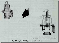
valve. When the pressure reaches the safety limit setting, the valve functions as a water relief valve and discharges the small amount of water which is expanded in the system (Fig. 54).
If both water and steam are present in a hot-water space heat ing boiler, the firing controls are probably malfunctioning or have completely broken down. This may result in runaway firing of the boiler which could cause the boiler water to reach steam-forming temperatures, creating a steam pressure condition. Under these circumstances, the relief valve functions as a steam safety relief valve. The steam is discharged at a rate or faster than the boiler can generate it, thus restoring system pressure to a safe level. Although these valves are steam rated and have an emergency Btu steam discharge capacity if runaway firing conditions occur, they should not be used for continuous steam service.
In order to be completely effective, the safety relief valves used on hot-water space heating boilers must be designed to dis charge the excessive water pressure created by thermal expansion and also the excessive steam pressure resulting from runaway emergency temperature conditions.
