ALTITUDE GAUGES
An altitude gauge mounted on the boiler is used to indicate the water level in open hot-water heating systems. The level (altitude) of the water is indicated on the gauge by the relative positions of two hands or arrows. One hand (usually black) is stationary, and is permanently set when the boiler is filled. The movable hand (usually red or white) is initially set in the same position as the stationary hand after the boiler has been filled with water. Its position will change as the water level in the boiler changes. This movable hand indicates the true level of the water. Efficient operation is being provided as long as the movable hand is directly above the stationary one.
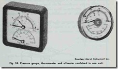
Fig. 55 shows a pressure gauge, thermometer and altimeter (altitude gauge) combined in one unit. These Marsh Ther-Alti Meters are used on residential hot-water space heating boilers. They provide water pressure readings from 0 to 30 psi (red field to 50 psi), corresponding altitude from 0 to 70 ft., and water tem perature from 60° to 320°F.
In closed hot-water heating systems, automatic valves are used to control boiler water level (see PRESSURE RELIEF VALVES and PRESSURE-REDUCING VALVES in this chapter).
AQUASTATS
An aquastat is a device commonly used on hot-water space boilers and some steam boilers to control temperature limit or to operate the circulator (hot-water heating system pump). It is similar in function to the pressure control on a steam boiler or the fan and limit control on a forced warm-air furnace.
Basically, an aquastat is an automatic switching device con sisting of a metal or liquid filled heat sensitive clement designed to detect temperature drop or rise of the boiler water. Aquastats can be strapped to the hot water supply riser or mounted so that the heat sensitive element is immersed in a boiler well.
The type of aquastat used in a heating installation generally depends upon whether it is designed to control temperature limit or to switch on the circulator. If the former is the case, the aqua stat will close on temperature drop and open on temperature rise. The aquastat will close on temperature rise if it is used to operate the circulator.
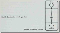
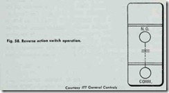
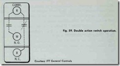
An example of a strap-on type aquastat is the ITT General Controls L-53 Strap-On Hot \Vater Control illustrated in Fig. 56. This type of aquastat responds to water temperature changes as conducted through the supply riser pipe wall to the temperature responsive base of the device. The enclosed switching is supplied in direct action (Fig. 57), reverse action (Fig. 58), and double action (Fig. 59) models. Consequently, these strap-on type aqua stats can be divided into three basic types depending upon their operating principles: (1) direct action types, (2) reverse action types, and (3) double action types.
A direct action (N.C.) type aquastat used as a high limit con trol must always be located on the supply riser where it will be subjected to the maximum boiler water temperature. Its location on the riser will therefore have to be as close to the boiler as pos sible, but ahead of any line shutoff valves.
Direct action type aquastats will open the circuit on tempera ture rise. Setting the adjustable scale pointer to a position on the scale will result in breaking the circuit (Fig. 60). The “cut-out” setting when used as a high limit control should be as low as possible and still insure proper heating in cold weather. An initial “cut-out” setting of 170°F is recommended for a gravity hot-water heating system. An initial setting of 200 °F is suggested for a forced hot-water (hydronic) heating system. The mechanical dif ferential of the control illustrated in Fig. 60 is nonadjustable and approximately l5°F.
A reverse action (N.O.) type aquastat should be mounted ahead of any valves or traps on the return line when it is used on a unit heater installation. It should be mounted on the largest riser from the boiler if it is used to prevent circulator operation when boiler water temperature is low. A reverse action type aquastat closes the circuit on temperature rise.
A double action (SPDT) type aquastat is used to start circu lator operation with a single switch actuation and to function as an operating control to maintain boiler water temperature. This type of aquastat should be mounted on the largest riser ahead of any valve, but at a point where it will be subjected to maximum boiler water temperatures. The double action type aquastat illustrated in Fig. 59 opens R to B contacts and closes R to W contacts on temperature rise at scale setting.
Another example of a strap-on aquastat is the Honeywell LA409A aquastat shown in Fig. 61. This is a nonimmcrsion, sur face mounted aquastat which functions as a high limit or safety control device in hot-water and steam heating systems, and which requires no tapping of the boiler or draining of the system. This aquastat is also available in a reverse action model to operate unit heater fans.
A strap-on aquastat can be mounted in any position. When mounting these aquastats, make absolutely certain that the pipe surface is clean and free of rust and corrosion. All rough and high spots should be filed smooth. Nothing should be allowed to inter fere with the operation of the temperature responsive base of the control.
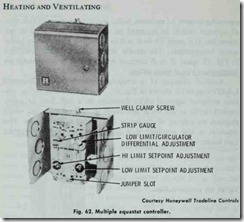
The Honeywell L6081A aquastat shown in Fig. 62 is used to control boiler water temperature in gas- and oil-fired hydronic heating systems. It has an immersion type liquid filled heat sensing element which actuates two snap switches. One switch operates as a high limit control, the other as a low limit and/or circulator control.
LOW-WATER CUTOFFS
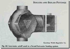
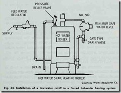
A low-water cutoff device such as the one shown in Fig. 63 can also be used in a hot-water heating system to provide protection against a low water level condition in the boiler resulting from runaway firing caused by malfunctioning controls or a break in the return piping. The low water cutoff device should be in stalled in the piping so that the raised line cast on the float cham ber body is on a level with the top of the boiler (Fig. 64). The drain valve located directly below the low-water cutoff should be opened periodically to flush mud and sediment from the float cpamber. It is recommended that this be done at least once a month.
WATER PRESSURE REDUCING VALVES
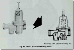
Most forced hot-water heating systems are equipped with a pressure-reducing valve which is designed to automatically feed water into the boiler when the pressure in the system drops below the valve setting. When the pressure returns to the minimum pres sure setting, the valve automatically closes. Thus, the function of a water pressure reducing valve is to keep the system automat ically filled with water at the desired operating pressure (Fig. 65).
