Water Systems
Water systems are more commonly used for heating than are steam systems. The advantages of water over steam include the fact that water is safer and more controllable than steam.
Water is safer because the system pressure is not determined by continuously balancing the boiler output with load, and because water does not have the capacity to expand at high velocity in all directions.
Water is more controllable for heating since the water temperature can easily be changed to modify the heat transfer.
Water System Design Issues: Pipe Construction
Water for heating and cooling is transferred in pipes that are generally made of steel, copper or iron. Steel is normally a less expensive material and is most popular for sizes over 1 inch. Copper is a more expensive material but it is very popular at 1 inch and narrower, due to its ease of installation. Long runs with few fittings favor steel, while the more complex connections to equipment favor the easy installation of copper.
Water System Design Issues: Pipe Distribution
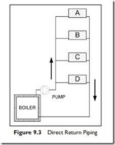
Heating or cooling water can be piped around a building in two ways, either “direct return” or “reverse return.” The direct return is diagrammed in Figure 9.3.
The simple circuit in Figure 9.3 consists of a boiler; four identical heaters A, B, C, D; a pump to drive the water round the circuit; and interconnecting pipes. When the pump is running, water will flow from the boiler to each heater, through the heater, and back to the pump, to be pumped around the circuit again.
There is friction to the water flowing through the pipes and the water favors the path of least resistance. The circuit: boiler : pump : heater D : boiler, is much shorter than the circuit: boiler : pump : heater A : boiler. As a result more water will flow through heater D than through heater A.
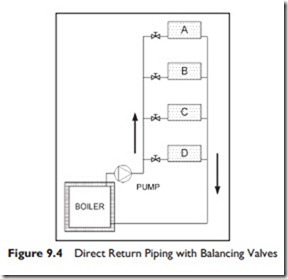
In order to have the same flow through all the heaters, extra resistance has to be added to heaters B, C and D. Adding balancing valves, as shown in Figure 9.4, makes this possible.
After the system has been installed, a balancing contractor will adjust the balancing valves to create an equal flow through heaters A and B, then an equal flow through heaters A and C and finally an equal flow through heaters A and D. This simple, step-by-step, procedure will produce the highest balanced set of flows for the four heaters.
The total flow may be more or less than design, but the flows will be equal. If the flow is more than required, it is possible, but difficult, to go back and rebalance to a specific lower flow.
In practice, a single balancing valve in the main loop, often between the pump and boiler, can be used to reduce the total flow. As the total flow is reduced, the flow in each heater will reduce in the same proportion. This circuit works well, once it has been balanced. On most systems, a valve is installed on each side of heaters so that the heater can be valved-off and repaired without having to shut down and drain the whole system.
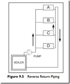
Let us now imagine that one of the heaters failed and in the process of removing it, the balancing valve is closed. When the heater has been replaced the question is “How much should the balancing valve be opened?” Did anyone take note of the valve position before it was moved? If not, the balancing valve will likely be left fully open. The system may work satisfactorily with the balance valve open, or, it may not. This problem of being dependent on balancing valves can largely be overcome by using a different piping arrangement, the reverse return as shown in Figure 9.5. Here the pipe length for the flow loop boiler : pump : heater : boiler is the same for all heaters. Verify this for yourself by tracing the water path through heater D and then the path through heater A. As a result, the flow will be the same in each heater; the piping is self-balancing.
The reverse-return piping costs more due to the additional return length of pipe. There are cases where the flow is critical, for example, direct expansion refrigeration heat pumps. In this case, the additional cost of reverse return piping is worthwhile. The maintenance staff only needs to fully open the valves to a unit to know it has full flow.
In circuits where exact balance is not critical, a system with direct return and balancing valves is a good choice.
Having considered the two main piping arrangements let us now go on to the flow of water and pumps.
Water System Design Issues: Flow
The resistance to water flow in pipes, called the head, is dependent on several factors including surface roughness, turbulence, and pipe size. When we design a system, we calculate the expected resistance for the design flow in each part of the circuit. The sum of the resistances gives the total resistance, or system head.
Under normal flow rates, the resistance rises by a factor of 1.85 to 1.9 as the flow rises (flow1.85 to flow1.9). Doubling the flow increases the resistance about three and a half times.
The actual head loss in pipes is normally read from tables, to avoid repetitive complex calculations. Based on this table data and the knowledge that the head is proportional to flow1.85 we can plot the system curve of flow or capacity, versus head.
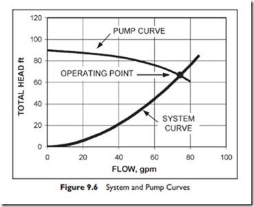
Pump manufacturers test their pumps to establish what flows the pump generates at a range of heads. At a particular pump speed, measured in revolutions per minute, rpm, they will measure the head with no flow, and again at increasing flows, or capacities. They can then plot the pump head against flow or capacity to produce a pump curve. A pump curve and calculated system curve are shown in Figure 9.6.
The pump curve in this figure shows a peak head of 90 feet with no flow that gradually drops to about 65 feet at 74 gallons per minute, gpm, where it crosses the calculated system curve. If the design calculations were correct, the operating point for this pump will be at the intersection of the two curves.
In practice, the system curve often turns out to be higher or lower than the calculated design. The effects of this, and remedies for it, are covered in the course ASHRAE Fundamentals of Water Systems.
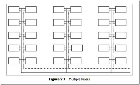
The layout of piping in a building is very dependent on load locations and where pipe access is available. Figure 8.8, in the last chapter, showed a single riser
in the building with a reverse return loop around every floor. This works well for heat pumps mounted in the ceiling, with the pipes running in the ceiling.
Conversely, it often does not work very well for equipment, such as radiators, fan coils and induction units, mounted near the floor at the perimeter of the building. For these, multiple risers around the building may be a better solution, as shown in Figure 9.7.
Having introduced piping layouts and pumps let us go on to consider the three main types of water circuits and some of their characteristics.
