Combination Water Heaters
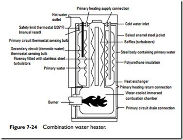
A combination water heater is designed to produce both domestic (potable) and space heating hot water from the same source. As shown in Figure 7-24, an inner stainless steel tank containing the domestic hot water supply is immersed inside an insulated outer tank containing the prime water used for space heating. The prime water in the outer tank is heated by a gas or oil burner. The heated prime water transfers its heat by convection to the domestic water supply stored in the inner tank. The two tanks are completely separate from one another, preventing the domestic and space heating waters from
mixing. Each combination water heater operates in conjunction with a circulating pump, expansion tank, pressure-reducing fill valve, and three-way zone valve. See Chapter 4, “Water Heaters” in Volume 3 for additional information about combination water heaters.
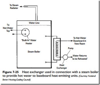
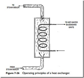
Steam can also be used as a source of heat in a hot-water heating system. If such is the case, then a heat exchanger (Figure 7-25) must be used to convert the steam to hot water before it reaches the heat- emitting units. The heat exchanger is commonly of the steel-shell and copper-tube design. The steam flows through the shell and the water through the tubes (Figure 7-26). The hot water returns to the steam boiler, where it is reheated and changed to steam again.
Control Components
The efficient and safe operation of a hot-water heating system requires the use of a variety of different types of controls, which can be roughly divided into either system-actuating controls (e.g., the room thermostat, burner controls, and circulating pump controls) or safety controls (e.g., high-limit controls, pressure-relief valves, and pressure-reducing valves).
The safety controls prevent damage to the system by shutting it down when pressure and temperature levels become excessive. The high-limit control, or aquastat, is an example of such a control. It is
a device designed to operate in conjunction with the circulating pumps and is located on the hot-water boiler. If the pressure or tem- perature of the hot water exceeds the design limits of the system, the system is shut down until conditions return to an acceptable level. Some aquastat relays provide multizone control when used with a separate circulator and a relay for each zone.
Another very important safety control for hot-water heating sys- tems are pressure-relief valves. These valves are designed to open when pressure in the boiler reaches a certain level and close when the pressure returns to a safe level again. Pressure-relief valves must be installed in accordance with current ASME or local codes.
These and other controls (e.g., main shutoff valves, pressure-reducing valves, and drain cocks) are described in considerable detail else- where in Chapter 15, “Steam and Hot-Water Space Heating Boilers” of this volume, and in Chapters 4, “Thermostats and Humidistats,” and 9, “Valves and Valve Installation” of Volume 2.
Pipe and Pipe Sizing
The tubing used in hydronic heating systems is made of copper, steel, plastic, or rubber. The size of the pipes or tubing used in these systems depends on the following two factors: (1) the flow rate of
the water and (2) the friction loss in the tubing. The flow rate of the water is measured in gallons per minute (gpm), and constant friction loss is expressed in thousandths of an inch for each foot of pipe length. For a description of the various types of tubing used in hydronic heating systems see the appropriate sections of Chapter 8, “Pipes, Pipe Fittings, and Piping Details” in Volume 2, which also describes the sizing methods used.
Expansion Tanks
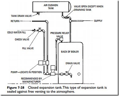
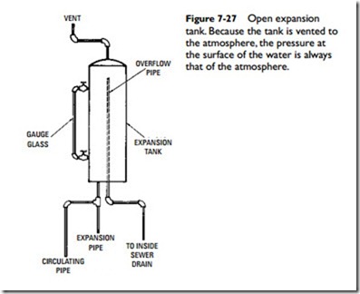
Expansion tanks (Figures 7-27 and 7-28) are installed in hot-water heating systems to provide for the expansion and contraction of the water as it changes in temperature. Water expands with the rise of temperature, and the excess volume of the water flows into the expansion tank.
Another feature of the expansion tank is that the boiling point of the water can be increased by elevating the tank. In other words, increasing the head (i.e., the difference in elevation between two
 points in a body of fluid) increases the pressure. As a result, the water can be heated to a higher temperature without generating steam, which, in turn, causes the radiators or other heat-emitting devices to give off more heat.
Both open and closed expansion tanks are used in hot-water heating systems. The open expansion tank is used on low-pressure systems, and the closed tank is used on high-pressure systems. Air in the tank above the water forms a cushion for increasing the pres- sure. As the temperature of the water rises, the water expands and flows into the tank, thus compressing the air and increasing the pressure.
The relation between pressure and volume changes of the air should be understood. According to Boyle’s law, at constant tem- perature the pressure of a gas varies inversely as its volume. Thus, when the volume is reduced by one-half, the pressure is doubled. This is not gauge pressure, but absolute pressure (the pressure mea- sured from true zero or point of no zero pressure).
In gravity hot-water heating systems, either closed or open piping arrangements can be used. In an open gravity system, the expansion tank is located at the highest point in the system (e.g.,
roof, attic, or top floor; see Figure 7-14). The expansion tank used in this piping arrangement is an open type with an overflow pipe located at the top. Provisions can be made to return the overflow water to the boiler or to discharge it through outside runoff drains.
In a closed gravity system, a closed, airtight expansion tank is located near the hot-water boiler (Figure 7-28). Higher pressures (and, consequently, higher water temperatures) result as pressure builds up in the system. Pressure-relief valves are installed on the main supply line to prevent the buildup of too much pressure.
Note
Hydronic heating systems are closed ones with expansion tanks located near the boiler.
