Loss in Doors and Windows
It is not easy to compute the coefficient of heat transmission (U-value) for a door, because door construction varies consider ably in size, thickness, and material. A fairly accurate rule-of thumb method is to use the U-value for a comparable size single pane glass window. If you wish to compute the coefficient of heat transmission for a door, the necessary data can be found in ASHRAE publications. The same source can be used for com puting the coefficients of heat transmission of windows.
Loss in Basements
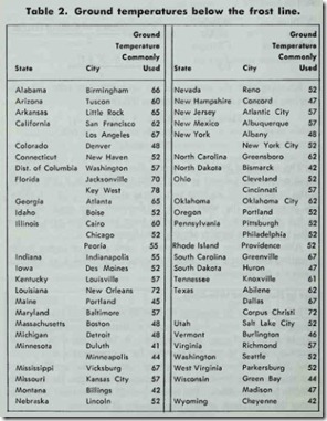
The amount of heat lost from a basement will depend upon a number of different variables. An important consideration, for example, is ground temperature, which will function as the “out door” design temperature in the heat loss transmission formula (see above). The ground temperature will vary with geographical Jocation (Table 2).
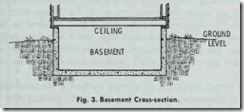
The usual method for calculating heat loss transmission through basement walls is to view them as being divided into two sections (Fig. 3). The upper section extends from the frost line to the basement ceiling and includes those portions of the wall exposed to outdoor air temperatures. The heat loss for this section of the basement wall is calculated in the same way that other surfaces exposed to the outside air are calculated. The section of the wall extending from the frost line to the basement floor and the floor itself can be calculated on the basis of the ground tem perature. The ground temperature is substituted for the outside design temperature when calculating heat loss.
Loss in Slab Construction
The heat loss for houses and small buildings constructed on concrete slab at or near grade level is computed on the basis of heat loss per foot of exposed edge. For example, a concrete slab measuring 20 ft. X 25 ft. would have an exposed edge of 90 ft. This represents the measurement completely around the perimeter of the exposed edge of the slab. The heat loss will depend upon the thickness of insulation along the exposed edge and the outside design temperature range. This type of information is available from ASHRAE publications. To obtain the heat loss in Btuh, sim ply multiply the total length of exposed edge by the heat loss in Btuh per lineal foot. For example, a 90 ft. exposed edge with 2- inch edge insulation at an outdoor design temperature of 35°F would be calculated as follows:
90 lin. ft. X 45 Btuh/lin. ft. = 4050 Btuh
Infiltration Heat Loss
During the heating season, a portion of heat loss is due to the infiltration of cooler outside air into the interior of the structure
through cracks around doors and windows and other openings that are not a part of the ventilating system. The amount of air entering the structure by infiltration is important in estimating the requirements of the heating system, but the composition of this air is equally important.
A pound of air is composed of both dry air and moisture particles which are combined (not mixed) so that each retains its individual characteristics. The distinction between these two basic components of air is important, because each is involved with a different type of heat: dry air with specific heat and moisture content with latent heat.
The heating system must be designed with the capability of warming the cooler infiltrated dry air to the temperature of the air inside the structure. The amount of heat required to do this is referred to as the sensible heat loss, and is expressed in BTU’s per hour. The two methods used for calculating heat loss by air infiltration are: (1) the crack method and (2) the air change method.
The Crack Afethod- The crack method is the most accurate means of calculating heat loss by infiltration, because it is based on actual air leakage through cracks around windows and doors, and takes into consideration the expected wind velocities in the area in which the structure is located. The air-change method (see below) does not consider wind velocities, which makes it a less accurate means of calculation.
Calculating heat loss by air infiltration with the crack method involves the following basic steps:
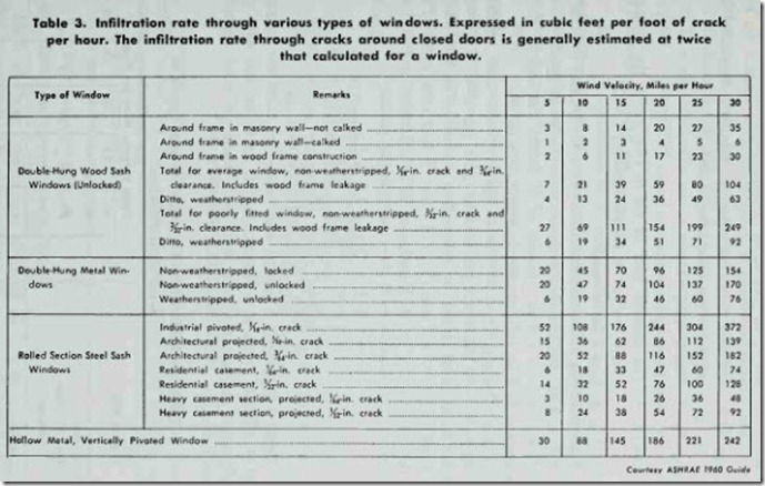
1. Determine the type of window or door (see Table 3).
2. Determine the wind velocity and find the air leakage from Table 3.
3. Calculate the lineal feet of crack.
4. Determine the design temperature difference.
The data obtained in these four steps are used in the following formula:
H = 0.018 X Q (t1 – t0) X L
Where:
H Heat loss, or heat required to raise the temperature of air leaking into the structure to the level of the indoor temperature (t1 ) expressed in Btu’s per hour.
Q Volume of air entering the structure expressed in cubic feet per hour (Step 2 above).
t1 Indoor temperature.
t0 Outdoor temperature.
0.018 The specific heat of air (0.240) times the density of the outdoor air (approximately 0.075).
L Lineal feet of crack.
Determine the infiltration heat loss per hour through the crack of a 3 x 5 ft. average double-hung, non-weatherstripped, wood window based on a wind velocity of 20 mph. The indoor tem perature is 70°F and the outdoor temperature is 20°F.
The air leakage for a window of this type at a wind velocity of 20 mph is 59 cubic feet per foot of crack per hour. This will be the value of Q in the air infiltration formula. The lineal feet of crack is (2 X 5) plus (3 X 3) , or 19 feet (the value of L in the formula). t1 = 70°F and to = 20°F. Substituting this data in the air infiltration formula gives the following results:
H = 0.018 X Q(t1 – t0) X L
= 0.018 X 59(70 – 20) X 19
= 1.062 X 50 X 19
= 1008.9 Btuh = 1009 Btuh
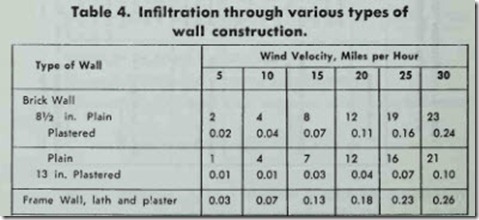
Table 4 represents a typical wall infiltration chart for a num ber of different types of wall construction. As is the case with air infiltration through windows, it is also based on wind velocity (see Table 3).
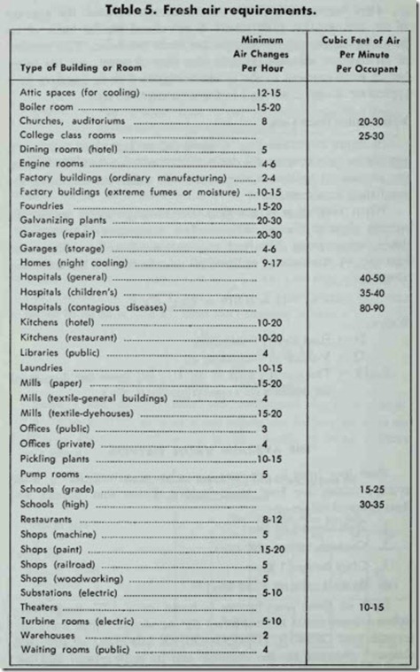
Air Change Method-In the air change method, the amount of air leakage (i.e. infiltration) is calculated on the basis of an assumed number of air changes per hour per room. The number of air changes will depend upon the type of room, and the num ber of walls exposed to the outdoors. Table 5 is an example of a typical air change chart used in the air change method.
Ventilation Heat Loss
In larger structures (e.g. commercial or industrial buildings) , ventilation is necessary for both health and comfort. In houses , the amount of infiltrated air is generally sufficient to supply the ventilation requirements.
When ventilation is provided, the heating system warms the outside air used for this purpose (i.e. ventilation) to the inside design temperature. The heat required will be equivalent to the heat lost by ventilation, and can be calculated with the following formula:
Where:
H = 0.018 X Q(t1 – t0)
H = Heat lost by ventilation.
Q = Volume of ventilation air.
0.018 = The specific heat of air (0.240) times the density of the outdoor air (approximately 0.075).
THE AVERAGE VALUE METHOD
Heat loss from a structure can also be calculated by using average values for four basic factors. These four factors and their assigned values are:
1. Wall factor (.32 Btu),
2. Contents factor (.02 Btu),
3. Glass factor (1 Btu),
4. Radiation factor (240 Btu).
Each of these four factors is based on a 1°F. temperature difference and must be multiplied by the design temperature difference (see DESIGN TEMPERATURE DIFFERENCE in this chapter) obtained for the structure and its geographical location.
The average value for each factor represents the amount of heat (in Btu’s) that will pass through one square foot of the ma terial in one hour. Thus .32 Btu will pass through a square foot of ordinary brick wall, or through a waH where the average frame construction is used in one hour. It should be stressed that these are average values useful in a simple and quick way of calculating heat Joss. The wall factor of .32 Btu’s varies for different kinds of walls, and heat loss calculations based on the use of average values will only be approximately accurate. More precise heat loss cal culations can be made by using coefficients of heat transmission (U-factors).
The glass factor (1 Btu) is used to represent the amount of heat that will pass through one square foot of glass in an hour.
The radiation factor (240 Btu) was originally used to represent the amount of heat in Btu given off by an ordinary free standing cast iron radiator on the basis of the square-foot area of heating surface per hour under average conditions. The average value of the radiation factor was based upon repeated test ob servations that the amount of heat given off by ordinary cast iron radiators per degree difference in temperature between the steam (or water) in the radiator and the air surrounding the radiator is about 1.6 Btu per square foot of heating surface. Taking this as a basis, a steam radiator under 21h lbs. pressure corresponds approximately to 220°F. and when surrounded by air having a 70°F. inside air temperature gives off heat at a rate of 240 Btu (220 – 70 X 1.6 = 240 Btu).
Radiators became so varied in design (with corresponding variations in the sizes of heating surface areas) that it became necessary to regard 240 Btu as a standard value.
Hot-water heating systems are planned on the basis of the Btu per hour capacity of each heat emitting unit. In steam heat ing systems, the radiation to be used is selected on the basis of the square foot EDR (Equivalent Direct Radiation) capacity of each unit. One square foot of EDR equals 240 Btu per hour. The EDR capacity of a space is expressed in square feet and may be determined by dividing the total heat required (expressed in Btu’s per hour) by 240. For example, a room requiring 12,000 Btu per hour to heat it would have a steam radiation requirement of 50 square feet of EDR capacity.
The steps involved in determining heat loss with the average value method are:
1. Decide upon the desired inside air temperature.
2. Obtain the winter outside design temperature of the location of the structure from published lists or a local weather bureau.
3. Determine the design temperature difference (the differ- ence between the temperatures found in Steps 1 and 2).
4. Calculate the volume of the structure or space.
5. Calculate the total area (in square feet) of window glass.
6. Calculate the total area of wall surface exposed to the outdoors.
7. Deduct the total area of window glass (Step 5) from the total area of wall surface exposed to the outdoors (Step 6).
8. Multiply the volume of the stntcture or space (Step 4) by the contents factor (.02) to determine the Btu re quired to raise the temperature of the volume an amount equal to the design temperature difference (Step 3).
9. Multiply the net wall surface area (Step 7) by the wall factor ( .32) to determine heat loss through the walls.
10. Multiply the total window glass surface area (Step 5) by the glass factor (1 ) to determine heat loss through glass.
11. Add the figures obtained in Steps 8-10 to obtain the total heat loss per hour for the structure or space (this is equal to the total heat required per hour).
The eleven steps outlined above might be more clearly under stood if shown in a sample problem.
Let’s assume that you must calculate the heat Joss for a space
14 ft. wide X 14 ft. long X 9 ft. high. 60 sq. ft. of window glass is equally divided between two exposed walls. The inside desired temperature is 70°F. and the winter outside design temperature is
– 10°F. Your procedure (corresponding step-by-step to those outlined above is as follows:
1. 70°F. inside desired temperature.
2. -10°F. winter outside design temperature.
80°F. design temperature difference.
1. 1764 cu. ft. volume (14 X 14 X 9).
2. 60 sq. ft. of glass.
3. 252 sq. ft. of wall surface exposed (2 sides) to the out doors (14 + 14) X 9 = 252).
4. 192 sq. ft. of net wall surface exposed (252 – 60 = 192).
8. 2822.4 Btu (1764 X .02 X 80).
9. 4915.2 Btu (192 X .32 X 80).
10. 4800 Btu (60 X 1 X 80).
11. 12,537.6 Btu (2822.4 + 4915.2 + 4800).
HEAT LOSS TABULATION FORMS
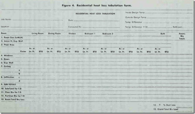
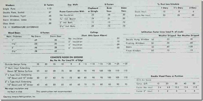
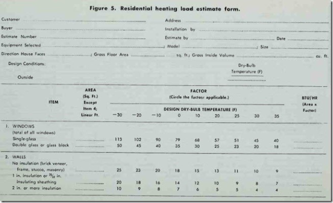
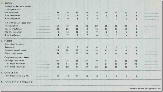
Manufactur rs of heating equipment will often provide heat loss tabulation forms and instructions for their use. Lists of the most commonly used U-values (or factors) are included with the forms. Figs. 5 and 6 show examples of these forms and instructions obtained from Amana Refrigeration, Inc.
ESTIMATING FUEL REQUIREMENTS AND HEATING COSTS
Estimating fuel requirements and heating costs is not an exact science. It involves too many variables to be anything other than an estimation. Moreover there are four different formulas used for making these calculations. Depending on which formula is used, it is possible to arrive at four different estimations of fuel requirements and heating costs for a specific situation. It is no wonder then that two competent engineers can submit estimates that will differ as widely as 30 percent or more. These facts are not offered to discourage anyone, but rather to present the true picture. Any attempt to calculate fuel requirements and heating costs will not produce precise figures-only an estimate. The problem is to make this estimate as close an approximation to the real situation as possible.
The four formulas used in calculating fuel requirements and heating costs are:
1. The Heat Loss Formula,
2. The Degree Day Formula,
INSTRUCTIONS FOR FIGS. 4 AND 5
Step 1. Room Size-list length, width and height.
Step 2. linear feet of Exposed Walls-total the length of all walls exposed to out· doors and enter the sum in the space provided.
Step 3. Floor Area-multiply length of room by width.
Step 4. Btu loss-windows
Factor Column-enter proper “U” factor from “window” table. Area Column-enter total of window area(s), width x height.
Btu Column-enter Btu loss for each degree of temperature difference ob tained from factor x area.
Step 5. Factor Column-enter proper “U” factor from “Door” table.
BTU Area Column-enter net door area obtained from width x height minus lOSS area of glass in door.
DOORS Btu Column-enter Btu loss for each degree of temperature difference obtained from factor x area.
Step 6. Btu loss-exposed Wall
Factor Column-enter proper “U” factor from “Exposed Wall” table.
Area Column-enter net wall area obtained from linear feet exposed wall (step 2) x ceiling height minus window and door area.
Btu Column-enter Btu l oss for each degree of temperature difference obtained from factor x area.
Step 7. Btu loss-ceiling
Factor Column-enter proper “U” factor from “Ceiling” table.
Area Column-enter ceiling area, length x width. (Usually the same as floor area (step 3).
Btu Columns-enter Btu loss for each degree of temperature difference obtained from factor x area.
Step 8. Btu loss-infiltration
In each class of infiltration: a, b, c, d take appropriate factor from “ln_fil tration” table x the linear feet of crack to obtain Btu per degree of temperature difference.
Step 9. Sub-Total Btu is the sum of Btu values. Steps 4 through 8 inclusive.
Step 10. Multiply Btu from step 9 by temperature difference taken from upper right corner of form.
Step 11. Btu loss-Floor
Factor from appropriate “Floor and Partition” table x area of floor =
Btu loss. If concrete floor on ground, use linear feet, step 2, in place of area of floor. NOTE: Basement assumed 60°.
Step 12. Partition Btu
Factor from “Floor and Partition” table x area of partition (length x height) gives partition Btu loss for temperature difference. A partition is a wall exposed to an un-heated area or room.
Step 13. Room Total Btu loss is the sum of Btu values steps 10 through 12 inclusive.
REPEAT THE STEPS FOR EACH ROOM IN THE HOME & ADD(STEP 14)TO OBTAIN THE GRAND TOTAL.
3. The NEMA Formula,
4. The Corrected Heat Loss Formula.
If one formula is used to calculate the fuel requirements and heating costs with one type of fuel (e.g. oil) and another formula is used for a second type (e.g. natural gas), the results are practically worthless for comparison purposes. For example, the NEMA Formula (created by the National Electric Manufacturers Association) will present the use of electric energy much more favorably if the results are compared with calculations for oil or natural gas based on the Heat Loss Formula. A true comparison is only possible when two fuels are both calculated with the same formula. Each of these formulas is described in the following sections.
