Ventilation and Combustion Air
A gas furnace requires an unobstructed supply of air for combustion. In the older standing-pilot furnaces, this combustion air sup- ply was commonly supplied through natural air infiltration (cracks in the walls and around windows and doors) or through ventilating ducts. Newer furnaces include a separate air combustion fan next to the burners to provide a sufficient supply of combustion air to the furnace. The houses are now too tightly constructed and well insulated for natural ventilation to provide enough air. These small air combustion fans or blowers are in addition to the large indoor blower on the furnace.
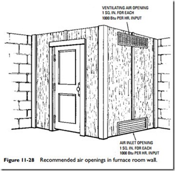
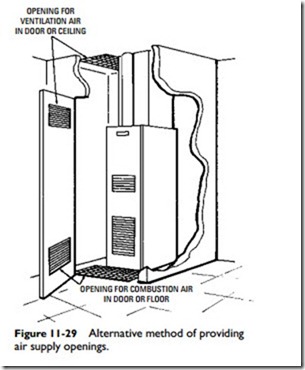
If a gas-fired furnace is located in an open area (basement or utility room) and the ventilation is relatively unrestricted, there should be a sufficient supply of air for combustion and draft hood dilution. On the other hand, if the heating unit is located in an enclosed furnace room or if normal air infiltration is effectively reduced by storm windows or doors, then certain provisions must be made to correct this situation. Figure 11-28 illustrates one type of modification that can be made to provide an adequate supply of combustion and ventilation air to a furnace room. As shown, two permanent grilles are installed in the walls of the furnace room, each of a size equal to 1 in2 of free area per 1000 Btu per hour of burner output. One grille should be located approximately 6 in
from the ceiling and the other one near the floor. A possible alter- native is to provide openings in the door, ceiling, or floor as shown in Figure 11-29.
If the furnace is located in a tightly constructed building, it should be directly connected to an outside source of air. A permanently open grille sized for at least 1 in2 of free area per 5000 Btu per hour of burner output should also be provided. Connection to an outside source of air is also recommended if the building contains a large exhaust fan.
Provisions for ventilation and combustion air are described in greater detail in Installation of Gas Appliances and Gas Piping (ASA Z21.30 and NFPA No. 54). These standards were adopted and approved by the National Fire Protection Association and the National Board of Fire Underwriters.
Venting
Provisions must be made for venting the products of combustion to the outside in order to avoid contamination of the air in the living or working spaces of the structure. The four basic methods of venting the products of combustion to the outside are:
1. Masonry chimneys
2. Low-heat Type A prefabricated chimneys
3. Type B gas vents
4. Type C vents
5. Wall venting
6. PVC pipe venting
Masonry and prefabricated chimneys are described in later sections (see Chimney and Chimney Troubleshooting in this chapter).
Warning
Any furnace that produces heat from the combustion process (that is, burning gas, oil, coal, or wood) can potentially pro- duce carbon monoxide gas as well. Carbon monoxide gas is odorless, invisible, and deadly toxic. The only safeguard against the accumulation of this gas before it reaches unsafe levels is to install a carbon monoxide detector.
Low-heat Type A flues are metal, prefabricated chimneys that have been tested and approved by Underwriters Laboratories, Inc. (UL). These chimneys are easier to install than masonry chimneys and are generally safer under abnormal firing conditions.
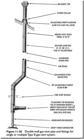
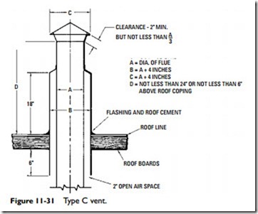
Type B gas vents (Figure 11-30) are listed by UL and are recommended for venting all standard gas-fired furnaces. They are not recommended for incinerators, combination gas-oil appliances, or appliances convertible to solid fuel. Check the furnace specifications for the type of vent to use. It will usually be AGA certified for use with a Type B gas vent. A Type C vent is used to vent gas-fired furnaces in attic installations (Figure 11-31).
Wall venting involves gas-fired appliances, which have their combustion process, combustion air supply, and combustion prod- ucts isolated from the space that is being heated. These appliances are generally vented through the wall.
High-efficiency gas furnaces vent the gases and other byproducts of the combustion process through PVC (plastic) pipe, not the metal pipe used with standing-pilot gas furnaces. The PVC exhaust pipe extends vertically through the roof or horizontally through a sidewall to the outdoors. The latter is the typical connection to a replacement furnace.
The PVC exhaust pipe must be firmly and securely supported. Weak or inadequate support can cause the piping to sag. A sagging horizontal exhaust vent pipe will cause condensate (water) to collect in low spots. The condensate cannot drain back down into the furnace and eventually builds up to a point where it blocks the exhaust vent. A blocked exhaust vent will cause the furnace to shut down.
Note
Provide at least a 1⁄4-inch per foot upward pitch for horizontal exhaust vent piping to allow the condensate to drain back down into the furnace. Never pitch the exhaust pipe down- ward toward the outdoors.
High-efficiency (condensing) furnaces should not be vented into a chimney. The exhaust gases from these furnaces are too cool to create a chimney draft. Unable to rise, they condense inside the chimney. The trapped condensate will eventually damage the chimney materials.
Flue Pipe
The flue is the passage through which the flue gases pass from the combustion chamber of the furnace (or boiler) to the outside. A flue is also referred to as a flue pipe, vent pipe, or vent connector.
The term appliance flue refers to the flue passages inside a furnace or boiler. A chimney flue is the vertical flue passage running up through the chimney. A vent connector is specifically the flue pas- sage between the heating unit and the chimney. It is also variously referred to as a chimney connector or smoke pipe. A flue outlet, or vent, is the opening in a furnace or boiler through which the flue gases pass.
Conventional Flue Construction Details
The flue pipe (vent pipe) connects the smoke outlet of the furnace with the chimney. It should never extend beyond the inner liner of the chimney and should never be connected to the flue of an open fireplace. Furthermore, flue connections from two or more sources should never enter the chimney at the same level from opposing sides.
The horizontal run of flue pipe should be pitched toward the chimney with a rise of at least 1⁄4 in per running foot. Some furnace manufacturers recommend as much as a 1-in minimum rise per running foot. Do not allow the horizontal run to exceed, in length, 75 percent of the vertical run. Vent pipe crossovers in an attic must not extend at an angle of less than 60° from the vertical.
At intervals, fasten the horizontal run of flue pipe securely with sheet-metal screws and support the pipe with straps or hangers to prevent sagging. Sagging can cause cracks to develop at the joints, which may result in releasing toxic flue gases into the living and working spaces of the structure.
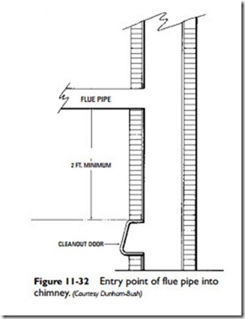
The point at which the flue pipe enters the chimney should be at least 2 ft above the cleanout opening of the chimney (Figure 11-32). The flue pipe must be the same size as the outlet of the flue collector
(furnace flue collar). Never install a damper in a flue pipe or reduce the size of the flue pipe. Run the flue pipe from the draft hood to the chimney in as short a distance as possible. All joints in the flue pipe should be made with the length nearest the furnace overlapping the other.
If excessive condensation is encountered, install a drip tee in place of an elbow. Never use dampers or other types of restrictors in the vent pipe. A minimum distance should be maintained between the vent pipe and the nearest combustible material.
When more than one appliance is vented into a common flue, the area of the common flue should be equal to the area of the largest flue plus 50 percent of the area of the additional flue.
PVC Vent Construction Details
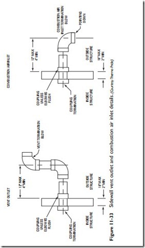
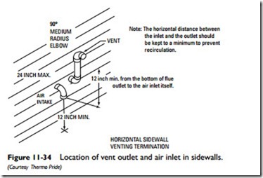
High-efficiency furnaces vent the byproducts of the combustion process through horizontal PVC piping extending from the furnace to an opening in an exterior sidewall. PVC piping is also used to bring combustion air from the outdoors to the furnace. Vent outlet and combustion air inlet details are illustrated in Figure 11-33. Figure 11-34 illustrates typical terminations for PVC piping on the outside of the sidewall. Note that the maxi- mum wall thickness through which both the vent and combustion air pipes can pass is 18 inches. The minimum thickness is 2 inches.
Carefully follow the local codes and ordinances plus the furnace manufacturer’s requirements when installing PVC vent and air intake piping. Note the following requirements:
• Install the bottom edge of the vent outlet termination elbow a minimum of 12 inches above the outlet of the combustion air termination elbow, as shown in Figure 11-32.
• Maintain a minimum horizontal distance of 4 ft between the outlet and inlet vents and any electric meters, gas meters, regulators, and relief devices.
• Insulate PVC vent pipe passing through an unheated space with 1.0-in-thick foil faced with fiberglass insulation.
• Cut PVC pipe at right angles with a hacksaw. Remove all burrs before installing the pipe.
• Seal PVC joints with a silicone caulk. Do not butt and glue cut pipe ends together. Do not use caulk to seal the PVC sleeve or coupling to the metal air intake collar on the furnace burner box.
Related posts:
Incoming search terms:
- Combustion Air Blowers mail
- HVAC Room Equipment mail
- furnace combustion air
- combustion air vent
- achiving outdoor ventilation air with furnaces
- codes for condensing gas furnace supply and exhaust air
- combustion air for furnace diy
- combustion air intake with exhaust pipe inside
- can furnace sheet metal vent pipe be transitioned to pvc
- combustion air cfm per btu natural gas
- CPVC Combustion air and gas vent
- boiler air intake tubing
- venilation for indoor natural gas burners
- Vacuum bright annealing heat treatment annealing furnace manufactures
- 5 plastic wall vents for natural gas exhaust fan
- is the furnaceair intake in the attic
- large insulated tube in furnace room
- combustion air space for High Efficiency Gas Furnace
- furnace room door vent
- Fireplaces furnaces mail
- Gas furnace manufactures
- piping furnace combusuon air
- combustion air for furnace
- ventilation in a boiler room that utility run on natural gas
- furnaces mail
- combustion air intake part for furnace
- combustion air intake from wall pvc length
- Steel Wire Bright Annealing Heat Treatment Furnace manufactures
- Tube Type Bright Annealing Furnace manufactures
- 6 pvc combustion air inlet termination firting
- combustion air piping material
- combustion air vent images
- factory manufacturer supply electric furnace heating wire manufactures
- pipe deteraltion in gas fired burner exshast piping
- should combustion air intake vent terminate in the attic
- combustion ventilation and dilution air explained
- Can i pipe my boiler air intake into the attick
- combustion air intake through wall to supply radiant heater
- A furnace that uses a fan to draw in and exhaust combustion air is a(n) _____
- champion gas furnace combustion air vent pipe noise
- combustion air intake for gas furnace
- combustion air grilles
- Attic Exhaust Fan Manufacturers mail
- Bell Type Gas Burning Annealing Furnace manufactures
- boiler house ventilation requirements
- can i use outside air for my coal furnace
- CDC060A936A illustrated furnace
- can you use hot air inside wood burning vent pipe to feed HVAC Air intake
- where are type c venting used
- can having furnace intake in attic cause poor air quality
