DESIGNING A PERIMETER SYSTEM
After the heat loss or heat gain has been calculated, the sum of these heat losses or heat gains will determine the size of the duct systems and the heating and cooling unit.
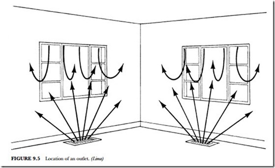
The three factors that ensure proper delivery and distribution of air within a room are location, type, and size of outlet. Supply outlets, if possible, should always be located to blanket every window and every out- side wall (see Figure 9.5). Thus, a register is recommended under each window. The outlet selected should be a diffuser whose air pattern is fan-shaped to blanket the exposed walls and windows.
The American Society of Heating, Refrigeration, and Air Conditioning Engineers (ASHRAE) furnishes a chart with the locations and load factors needed for the climate of each major city in the United States. The chart should be followed carefully. The type of house, the construction materials, location, room sizes, and exposure to sun and wind are important factors. With such information, you can determine how much heat will be dissipated. You can also determine how much cooling will be lost in a building. The ASHRAE Handbook of Fundamentals lists the information needed to compute the load factors.
Calculate the heat loss or heat gain of the room; divide this figure by the number of outlets to be installed. From this you can determine the Btu/h required of each outlet. Refer to the performance data furnished by the manufacturer to determine the size the outlet should be. For residential application, the size selected should be large enough so that the Btu/h capacity on the chart falls to the side where the quiet zone is indi- cated. There is still a minimum vertical throw of 6 feet where cooling is involved.
Locating and Sizing Returns
Properly locating and sizing return air grilles is important. It is generally recommended that the returns be installed in high sidewalls or the ceiling. They should be in one or more centrally located places. This de- pends upon the size and floor plan of the structure. Although such a design is preferred, low returns are acceptable for heating.
To minimize noise, care must be taken to size the return air grille correctly. The blower in the equipment to be used is rated in cfm by the manufacturer. This rating can usually be found in the specification sheets. Select the grille or grilles necessary to handle this cfm.
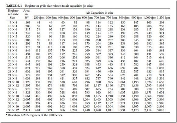
The grille or grilles selected should deliver the necessary cfm for the air to be conditioned. The throw should reach approximately three-quarters of the distance from the outlet to the opposite wall (see Figure 9.2). The face velocity should not exceed the recommended velocity for the application (see Table 9.1). The
drop should be such that the air stream will not fall into the occupied zone. The occupied zone is generally thought of as 6 feet above floor level.
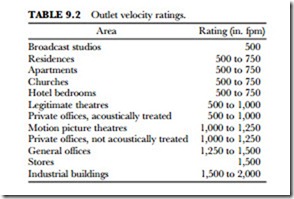
The sound caused by an air outlet in operation varies in direct proportion to the velocity of the air passing through it. Air velocity depends partially on outlet size. Table 9.2 lists recommendations for outlet velocities within safe sound limits for most applications.
Air-Flow Distribution
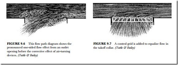
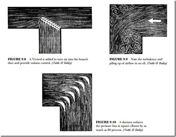
Bottom or side outlet openings in horizontal or vertical supply ducts should be equipped with adjustable flow-equalizing devices. Figure 9.6 indicates the pronounced one-sided flow effect from an outlet opening. This is before the corrective effect of air-turning devices. A control grid is added in Figure 9.7 to equalize flow in the takeoff collar. A Vectrol® is added in Figure 9.8 to turn air into the branch duct and provide volume control. Air-turning devices are recommended for installation at all outlet collars and branch duct connections.
Square unvaned elbows are also a source of poor duct distribution and high-pressure loss. Non-uniform flow in a main duct, occurring after an unvaned ell, severely limits the distribution of air into branch ducts in the vicinity of the ell. One side of the duct may be void, thus starving a branch duct. Conversely, all flow may be stacked up on one side. This requires dampers to be excessively closed, resulting in higher sound levels.
Flow diagrams show the pronounced turbulence and piling up of airflow in an ell (see Figure 9.9). Duc- turns reduce the pressure loss in square elbows as much as 80 percent. Their corrective effect is shown in Figure 9.10.
Selection of Diffusers and Grilles
The selection of a linear diffuser or grille involves the job condition requirements, judgment, and performance- data analysis. Diffusers and grilles should be selected and sized according to the following characteristics:
• Type and style
• Function
• Air-volume requirement
• Throw requirement
• Pressure requirement
• Sound requirement
The air volume per diffuser or grille is that which is necessary for the cooling, heating, or ventilation requirements of the area served by the unit. The air volume required, when related to throw, sound, or pressure design limitations, determines the proper diffuser or grille size.
Generally, air volumes for internal zones of building spaces vary from 1 to 3 cfm per square foot of floor area. Exterior zones require higher air volumes of 2.5 to 4 cfm per square foot. In some cases, only the
heating or cooling load of the exterior wall panel or glass surface is to be carried by the distribution cen- ter. Then, the air volume per linear foot of diffuser or grille will vary from 20 to 200 cfm, depending on heat-transfer coefficient, wall height, and infiltration rate.
Throw and occupied-area air location are closely related. Both could be considered in the analysis of specific area requirements. The minimum-maximum throw for a given condition of aeration is based upon a terminal velocity at that distance from the diffuser. The residual room velocity is a function of throw to terminal velocity. Throw values are based on terminal velocities ranging from 75 to 150 fpm with corresponding residual room velocities of 75 to 150 fpm. The diffuser or grille location, together with the air pattern selected, should generally direct the air path above the occupied zone. The air path then induces room air along its throw as it expands in cross-section. This equalizes temperature and ve- locity within the stream. With the throw terminating in a partition or wall surface, the mixed air path further dissipates energy.
Ceiling-mounted grilles and diffusers are recommended for vertical down patterns. Some locations in the room may need to be cooler than others. Also, some room locations may be harder to condition because of air-flow problems. These grilles are used in areas adjacent to perimeter wall locations that require localized spot conditioning. Ceiling heights of 12 feet or greater are needed. The throw for vertical projection is greatly affected by supply air temperature and proximity of wall surfaces.
Sidewall-mounted diffusers and grilles have horizontal values based on a ceiling height of 8 to l0 feet. The diffuser or grille is mounted approximately 1 foot below the ceiling. For a given throw, the room air motion will increase or decrease inversely with the ceiling height. For a given air-pattern setting and room air mo- tion, the listed minimum-maximum throw value can be decreased by l foot for each 1-foot increase in ceil- ing height above 10 feet. Throw values are furnished by the manufacturer. When sidewall grilles are in- stalled remote from the ceiling (more than 3 feet away), reduce rated throw values by 20 percent.
Sill-mounted diffusers or grilles have throw values based on an 8- to 10-foot ceiling height with the outlet installed in the top of a 30-inch-high sill. For a given throw, the room air motion will change with the ceil- ing height. For a given air-pattern setting and room air motion, the listed minimum-maximum throw value can be decreased by 2 feet for each 1-foot increase in ceiling height above 10 feet. Decrease 1 foot for each 1-foot decrease in sill height.
The minimum throw results in a room air motion higher than that obtained when utilizing the maximum throw. Thus, 50 fpm rather than 35 fpm is the air motion. The listed minimum throw indicates the mini- mum distance recommended. The minimum distance is from the diffuser to a wall or major obstruction, such as a structural beam. The listed maximum throw is the recommended maximum distance to a wall or major obstruction. Throw values and the occupied area velocity for sidewall grilles and ceiling diffusers are based on flush ceiling construction, providing an unobstructed air-stream path. The listed maximum throw times 1.3 is the complete throw of the air stream where the terminal velocity equals the room air velocity. Rated occupied-area velocities range from 25 to 35 fpm for maximum listed throws and 35 to 50 fpm for minimum listed throws.
Cooled air drop or heated-air rise are of practical significance when supplying heated or cooled air from a sidewall grille. If the throw is such that the air stream prematurely enters the occupied zone, considerable draft may be experienced. This is due to incomplete mixing. The total airdrop must be considered when the wall grille is located a distance from the ceiling. Cooled air drop is controlled by spacing the wall grille from the ceiling and adjusting the grilles upward 15 inches. Heated-air rise contributes significantly to tempera- ture stratification in the upper part of the room.
The minimum separation between grille and ceiling must be 2 feet or more. The minimum mounting sep- aration must also be 2 feet or more. The minimum mounting height should be 7 feet.
The diffuser or grille minimum pressure for a given air volume is reflected in ultimate system fan horse- power requirements. A diffuser or grille with a lower pressure rating requires less total energy than a unit with a higher pressure rating for a given air volume and effective area. Diffusers and grilles of a given size with lower pressure ratings usually have a lower sound level rating at a specified air volume.
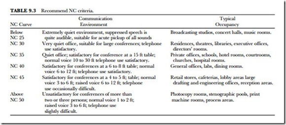
Diffusers and grilles should be selected for the recommended noise criteria rating for a specific applica- tion. The data for each specific diffuser or grille type contains an NC rating. Table 9.3 lists recommended noise criteria (nc) and area of application.
High velocities in the duct or diffuser typically generate air noise. The flow turbulence in the duct and the excessive pressure reductions in the duct and diffuser system also generate noise. Such noise is most appar- ent directly under the diffuser. Room background levels of nc 35 and less provide little masking effect. Any noise source stands out above the background level and is easily detected.
Typically, air noise can be minimized by the following procedures:
• Limiting branch-duct velocities to 1,200 fpm
• Limiting static pressure in branch ducts adjacent to outlets to 0.15 inches H2O
• Sizing diffusers to operate at outlet jet velocities up to 1,200 fpm (neck velocities limited to 500 to 900 fpm) and total pressures of 0.10 inches H2O
• Using several small diffusers (and return grilles) instead of one or two large outlets or inlets that have a higher sound power
• Providing low-noise dampers in the branch duct where pressure drops of more than 0.20 inches of water must be taken
• Internally lining branch ducts near the fan to quiet this noise source
• Designing background sound levels in the room to be a minimum of nc 35 or nc 40
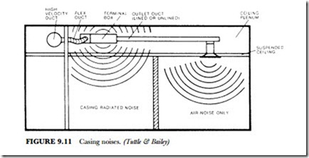
Casing noise differs from air noise in the way it is generated. Volume controllers and pressure-reducing dampers generate casing noise. Inside terminal boxes are sound baffles, absorbing blankets, and orifice re- strictions to eliminate line of sight through the box. All these work to reduce the generated noise before the air and air noise discharge from the box into the outlet duct. During this process, the box casing is vibrated by the internal noise. This causes the casing to radiate noise through the suspended ceiling into the room (see Figure 9.11).
Locating Terminal Boxes
In the past, terminal boxes and ductwork were separated from the room by dense ceilings. These ceilings prevented the system noise from radiating into the room. Plaster and taped sheetrock ceilings are examples of dense ceilings. Current architectural practice is to utilize lightweight (and low-cost) decorative suspended ceilings. These ceilings are not dense. They have only one-half the resistance to noise transmission that plaster and sheetrock ceilings have. Exposed tee-bar grid ceilings with 2 X 4 glass fiber pads and perforated metal pan ceilings are examples. The end result is readily apparent. Casing radiated noise in lightweight modern buildings is a problem.
Terminal boxes can sometimes be located over noisy areas (corridors, toilet areas, machine-equipment rooms) rather than over quiet areas. In quiet areas casing noise can penetrate the suspended ceiling and be- come objectionable. Enclosures built around the terminal box (such as sheetrock or sheet lead over a glass- fiber blanket wrapped around the box) can reduce the radiated noise to an acceptable level.
However, this method is cumbersome and limits access to the motor and volume controllers in the box. It depends upon field conditions for satisfactory performance and is expensive. Limiting static pressure in the branch ducts minimizes casing noise. This technique, however, limits the flexibility of terminal-box sys- tems. It hardly classifies as a control.
Vortex Shedding
Product research in controlling casing noise has developed a new method of reducing radiated noise. The technique is known as vortex shedding. When applied to terminal boxes, casing radiated noise is dramati- cally lowered. Casing-radiation-attenuation vortex shedders (CRA) can be installed in all single- or dual- duct boxes up to 7000 cfm, both constant volume or variable volume, with or without reheat coils. CRA de- vices provide unique features and the following benefits:
• No change in terminal box size; box is easier to install in tight ceiling plenums to ensure minimum casing noise under all conditions
• Factory-fabricated box and casing noise eliminator, a one-piece assembly, reduces cost of installation: only one box is hung, and only one duct connection is made
• Quick-opening access door is provided in box to assure easy and convenient access to all operating parts without having to cut and patch field-fabricated enclosures
• Equipment is laboratory-tested and performance-rated, and engineering measurements are made in accordance with industry standards, thus, on-job performance is ensured; quiet rooms result and owner satisfaction is assured
Return Grilles
Return air grilles are usually selected for the required air volume at a given sound level or pressure value. The intake-air velocity at the face of the grille depends mainly on the grille size and the air volume.
The grille style and damper setting have a small effect on this intake velocity. The grille style, however, has a very great effect on the pressure drop. This, in turn, directly influences the sound level.
The intake velocity is evident only in the immediate vicinity of the return grille. It cannot influence room air distribution. Recent ASHRAE research projects have developed a scientific computerized method of re- lating intake-grille velocities, measured 1 inch out from the grille face, to air volume. Grille measuring fac- tors for straight, deflected-bar, open, and partially closed dampers are in the engineering data furnished with the grille.
It still remains the function of the supply outlets to establish proper coverage, air motion, and thermal equilibrium. Because of this, the location of return grilles is not critical, and their placement can be largely a matter of convenience. Specific locations in the ceiling may be desirable for local heat loads or smoke ex- haust, or a location in the perimeter sill or floor may be desirable for an exterior-zone intake under a win- dow wall section. It is not advisable to locate large centralized return grilles in an occupied area. The large mass of air moving through the grille can cause objectionable air motion for nearby occupants.
Return air grilles should be selected for static pressures. These pressures will provide the required nc rat- ing and conform to the return-system performance characteristics. Fan sound power is transmitted through the return-air system as well as the supply system. Fan silencing may be necessary or desirable in the return side. This is particularly so if silencing is being considered on the supply side.
Transfer grilles venting into the ceiling plenum should be located remotely from the plenum noise source. The use of a lined sheet-metal elbow can reduce transmitted sound. Lined elbows on vent grilles and lined common ducts on ducted return grilles can minimize “cross talk” between private offices.
The spread of an unrestricted air stream is determined by the grille-bar deflection. Grilles with vertical face bars at 0-degree deflection will have a maximum throw value. As the deflection setting of vertical bars is increased, the air stream covers a wider area and the throw decreases.
Registers are available with adjustable valves. An air-leakage problem is eliminated if the register has a rubber gasket mounted around the grille. When it pulls up tightly against the wall, an airtight seal is made. This helps to eliminate noise. The damper has to be cam-operated so that it will stay open and not blow shut when the air comes through.
On some registers, a simple tool can be used to change the direction of the deflection bars. This means that adjusting the bars in the register can result in a number of deflection patterns.
Fire and Smoke Dampers
Ventilating, air conditioning, and heating ducts provide a path for fire and smoke, which can travel throughout a building. The ordinary types of dampers that are often installed in these ducts depend on grav- ity-close action or spring-and-level mechanisms. When their releases are activated, they are freed to drop inside the duct.
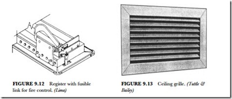
A fusible link attachment to individual registers also helps control fire and smoke. Figure 9.12 shows a fusible-link register. The link is available with melting points of 160 degrees F (71.1 degrees C) or 212 de- grees F (100 degrees C). When the link melts, it releases a spring that forces the damper to a fully closed position. The attachment does not interfere with damper operation.
Fire and smoke safety concepts in high-rise buildings are increasingly focusing on providing safety havens for personnel on each floor. This provision is to optimize air flow to or away from the fire floor or adjacent floors. Such systems require computer-actuated smoke dampers. Dampers are placed in supply and return ducts that are reliable. They must be tight-closing and offer minimum flow resistance when fully open.
Ceiling Supply Grilles, Registers, and Diffusers
Some ceiling grilles and registers have individually adjustable vanes. They are arranged to provide a one- way ceiling air pattern. They are recommended for applications in ceiling and sidewall locations for heat- ing and cooling systems. They work best where the system has 0.75 to 1.75 cfm per square foot of room area (see Figure 9.13).
Some supply ceiling grilles and registers have individually adjustable curved vanes. They are arranged to provide a three-way ceiling air pattern. The vertical face vanes are a three-way diversion for air. A horizontal pattern with the face vanes also produces a three-way dispersion of air. These grilles and registers are recommended for applications in ceiling locations for heating and cooling systems handling 1.0 to 2.0 cfm per square foot of room area.
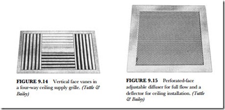
Figure 9.14 shows a grille with four-way vertical face vanes. Horizontal face vanes are also available. They, too, are adjustable individually for focusing an air stream in any direction. Both the three-way and four-way pattern grilles can be adjusted to a full or partial down blow position. The curved streamlined vanes are adjusted to a uniform partially closed position. This deflects the air path while retaining an effective area capacity of 35 percent of the neck area. In the full down blow position, grille effective area is in- creased by 75 percent.
Perforated adjustable diffusers for ceiling installation are recommended for heating and cooling (see Fig- ure 9.15). They are also recommended for jobs requiring on-the-job adjustment of air diffusion patterns.
Full-flow square or round necks have expanded metal air-pattern deflectors. They are adjustable for four-, three-, two-, or one-way horizontal diffusion patterns. This can be done without change in the air volume, pressure, or sound levels. These deflectors and diffusers have high diffusion rates. The result is rapid tem- perature and velocity equalization of the mixed air mass well above the zone of occupancy. They diffuse efficiently with six to eighteen air changes per hour.
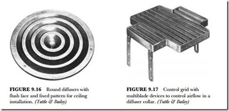
There are other designs in ceiling diffusers. The type shown in Figure 9.16 is often used in a supermarket or other large store. Here, it is difficult to mount other means of air distribution. These round diffusers with
a flush face and fixed pattern are for ceiling installation. They are used for heating, ventilating, and cooling. They are compact and simple flush diffusers. High induction rates result in rapid temperature and velocity equalization of the mixed air mass. Mixing is done above the zone of occupancy.
Grids are used and sold as an accessory to these diffusers. The grid (Figure 9.17) is a multi-blade device designed to ensure uniform airflow in a diffuser collar. It is individually adjustable. The blades can be moved to control the air stream precisely.
For maximum effect, the control grid should be installed with the blades perpendicular to the direction of approaching airflow. Where short collars are encountered, a double bank of control grids is recommended. The upper grid is placed perpendicular to the branch duct flow. The lower grid is placed parallel to the branch duct flow. The control grid is attached to the duct collar by means of mounting straps. It is commonly used with volume dampers.
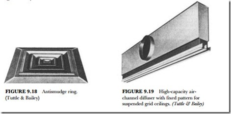
The antismudge ring is designed to cause the diffuser discharge-air path to contact the ceiling in a thin- layered pattern. This minimizes local turbulence, the cause of distinct smudging (see Figure 9.18).
For the best effect, the antismudge ring must fit evenly against the ceiling surface. It is held in position against the ceiling by the diffuser margin. This eliminates any exposed screws.
Air-channel supply diffusers are designed for use with integrated air-handling ceiling systems. They are adaptable to fit between open parallel tee bars. They fit within perforated or slotted ceiling runners. The ap- pearance of the integrated ceiling remains unchanged regardless of the size of the unit. They are painted out to be invisible when viewing the ceiling. These high-capacity diffusers provide a greater air-handling capa- bility (see Figure 9.19).
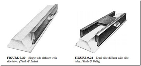
The luminaire is a complete lighting unit. The luminaire diffuser fits close to the fluorescent lamp fixtures in the ceiling. The single-side diffuser with side inlet is designed to provide single-side concealed air distribution (see Figure 9.20). The diffuser is designed with oval-shaped side inlets and inlet dampers and pro- vides effective single-point dampering.
Dual-side diffusers with side inlets are designed to provide concealed air distribution. Note the crossover from the oval side inlet to the other side of the diffuser. This type of unit handles more air and spreads it more evenly when used in large areas (see Figure 9.21). This type of diffuser is also available with an insula- tion jacket when needed.
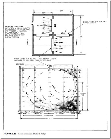
Figure 9.22 illustrates the airflow from ceiling diffusers. The top view illustrates the motion from the dif- fuser. The side view shows how the temperature differential is very low. Note that the temperature is 68 de- grees F near the ceiling and sidewall and 73 degrees F on the opposite wall near the ceiling.
Linear Grilles
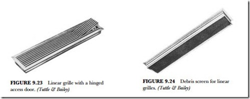
Linear grilles are designed for installation in the sidewall, sill, floor, and ceiling. They are recommended for supplying heated, ventilated, or cooled air and for returning or exhausting room air (see Figure 9.23).
When installed in the sidewall near the ceiling, linear grilles provide a horizontal pattern above the occupied zone. Core deflections of 15 and 30 degrees direct the air path upward to overcome the drop effect resulting from cool primary air.
When installed in the top of a sill or enclosure, linear grilles provide a vertical up pattern. This is effective in overcoming uncomfortable cold downdrafts. It also offsets the radiant effect of glass surfaces. Core deflections of 0 and 15 degrees directed toward the glass surface provide upward airflow to the ceiling and along the ceiling toward the interior zone.
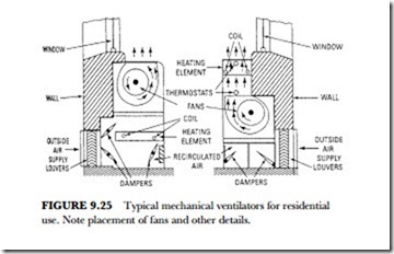
When installed in the ceiling, linear grilles provide a vertical downward air pattern. This pattern is effective in projection heating and in cooling the building perimeter from ceiling heights above 13 to 15 feet. Application of down-flow primary air should be limited to ensure against excessive drafts at the end of the throw. Core deflections of 0, 15, and 30 degrees direct the air path angularly downward as required. Debris screens can be integrally attached (see Figure 9.24).
Fans and Mechanical Ventilation
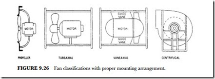
Mechanical ventilation differs from natural ventilation mainly in that the air circulation is performed by mechanical means (such as fans or blowers). In natural ventilation, the air is caused to move by natural forces. In mechanical ventilation the required air changes are affected partly by diffusion but chiefly by positive currents put in motion by electrically operated fans or blowers, as shown in Figure 9.25. Fresh air is usually circulated through registers connected with the outside and warmed as it passes over and through the intervening radiators.
The volume of air required is determined by the size of the space to be ventilated and the number of times per hour that the air in the space is to be changed. In many cases, existing local regulations or codes will govern the ventilating requirements. Some of these codes are based on a specified amount of air per person and others on the air required per square foot of floor area.
The various devices used to supply air circulation in air-conditioning applications are known as fans, blowers, exhausts, or propellers. The different types of fans may be classified with respect to their construction as follows:
• Propeller
• Tube axial
• Vane axial
• Centrifugal
A propeller fan consists essentially of a propeller or disk-type wheel within a mounting ring or plate and includes the driving-mechanism supports for either belt or direct drive. A tube axial fan consists of a propeller or disk-type wheel within a cylinder and includes the driving-mechanism supports for either belt drive or direct connection. A vane axial fan consists of a disk-type wheel within a cylinder and a set of air-guide vanes located before or after the wheel. It includes the driving-mechanism supports for either belt drive or direct connection. A centrifugal fan consists of a fan rotor or wheel within a scroll-type housing and includes the driving-mechanism supports for either belt drive or direct connection. Figure 9.26 shows the mounting arrangements.
Fan performance may be stated in various ways, with the air volume per unit time, total pressure, static pressure, speed, and power input being the most important. The terms, as defined by the National Association of Fan Manufacturers, are as follows:
• Volume handled by a fan is the number of cubic feet of air per minute expressed as fan-outlet conditions
• Total pressure of a fan is the rise of pressure from fan inlet to fan outlet
• Velocity pressure of a fan is the pressure corresponding to the average velocity determination from the volume of airflow at the fan outlet area
• Static pressure of a fan is the total pressure diminished by the fan-velocity pressure
• Power output of a fan is expressed in horsepower and is based on fan volume and the fan total pressure
• Power input of a fan is expressed in horsepower and is measured as horsepower delivered to the fan shaft
• Mechanical efficiency of a fan is the ratio of power output to power input
• Static efficiency of a fan is the mechanical efficiency multiplied by the ratio of static pressure to total pressure
• Fan-outlet area is the inside area of the fan outlet
• Fan-inlet area is the inside area of the inlet collar
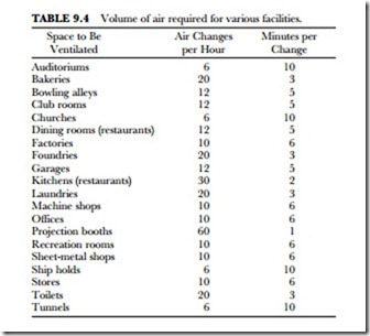
The volume of air required is determined by the size of the space to be ventilated and the number of times per hour that the air in the space is to be changed. Table 9.4 shows the recommended rate of air change for various types of spaces.
In many cases, existing local regulations or codes will govern the ventilating requirements. Some of these codes are based on a specified amount of air per person and on the air required per square foot of floor area. Table 9.4 should serve as a guide to average conditions. Where local codes or regulations are involved, they should be taken into consideration. If the number of persons occupying the space is larger than would be normal for such a space, the air should be changed more often than shown.
The horsepower required for any fan or blower varies directly as the cube of the speed, provided that the area of the discharge orifice remains unchanged. The horsepower requirements of a centrifugal fan generally decrease with a decrease in the area of the discharge orifice if the speed remains unchanged. The horse- power requirements of a propeller fan increase as the area of the discharge orifice decreases if the speed re- mains unchanged.
Whenever possible, the fan wheel should be directly connected to the motor shaft. This can usually be accomplished with small centrifugal fans and with propeller fans up to about 60 inches in diameter. The
deflection and the critical speed of the shaft, however, should be investigated to determine whether or not it is safe.
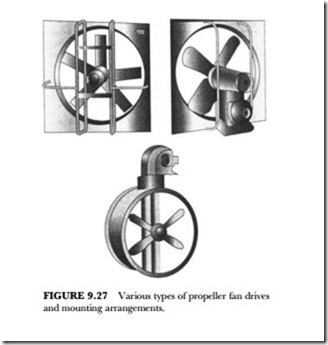
When selecting a motor for fan operation, it is advisable to select a standard motor one size larger than the fan requirements. It should be kept in mind, however, that direct-connected fans do not require as great a safety factor as do belt-driven units. It is desirable to employ a belt drive when the required fan speed or horsepower is in doubt, since a change in pulley size is relatively inexpensive if an error is made (see Figure 9.27).
Directly connected small fans for single-phase AC motors of the split-phase, capacitor, or shaded-pole type usually drive various applications. The capacitor motor is more efficient electrically and is used in districts where there are current limitations. Such motors, however, are usually arranged to operate at one speed. With such a motor, if it is necessary to vary the air volume or pressure of the fan or blower, the throttling of air by a damper installation is usually made.
In large installations (such as when mechanical draft fans are required), various drive methods are used, including: a slip-ring motor to vary the speed and a constant-speed, directly connected motor, which, by means of movable guide vanes in the fan inlet serves to regulate the pressure and air volume.
Most often, the service determines the type of fan to use. When operation occurs with little or no resist- ance, and particularly when no duct system is required, the propeller fan is commonly used because of its simplicity and economy in operation. When a duct system is involved, a centrifugal or axial type of fan is usually employed. In general, centrifugal and axial fans are comparable with respect to sound effect, but axial fans are somewhat lighter and require considerably less space. The following information is usually required for proper fan selection:
• Capacity requirement in cubic feet per minute
• Static pressure or system resistance
• Type of application or service
• Mounting arrangement of system
• Sound level or use of space to be served
• Nature of load and available drive
The various fan manufacturers generally supply tables or characteristic curves that ordinarily show a wide range of operating particulars for each fan size. The tabulated data usually include static pressure, outlet ve- locity, revolutions per minute, brake horsepower, tip or peripheral speed, and so on.
The numerous applications of fans in the field of air conditioning and ventilation are well known, partic- ularly to engineers and air-conditioning repair and maintenance personnel. The various fan applications are as follows:
• Attic fans
• Circulating fans
• Cooling-tower fans
• Exhaust fans
• Kitchen fans
Exhaust fans are found in all types of applications, according to the American Society of Heating and Ventilating Engineers. Wall fans are predominantly of the propeller type, since they operate against little or no resistance. They are listed in capacities from 1,000 to 75,000 feet3/minute. They are sometimes incorporated in factory-built penthouses and roof caps or provided with matching automatic louvers. Hood exhaust fans involving ductwork are predominantly centrifugal, and are used especially in handling hot or corrosive fumes.
Spray-booth exhaust fans are frequently centrifugal, especially if built into self-contained booths. Tube axial fans lend themselves particularly well to this application when suspension in a section of ductwork is advantageous. For such applications built-in cleanout doors are desirable.
Circulating fans are invariably propeller or disk-type units and are made in a vast variety of blade shapes and arrangements. They are designed for appearance as well as utility. Cooling-tower fans are predominantly of the propeller type. However, axial types are also used for packed towers, and occasionally a centrifugal fan is used to supply draft. Kitchen fans for domestic use are small propeller fans arranged for win- dow or wall mounting and with various useful fixtures. They are listed in capacity ranges from 300 to 800 feet3/minute.
Attic fans are used during the summer to draw large volumes of outside air through the house or build- ing whenever the outside temperature is lower than that of the inside. It is in this manner that the relatively cool evening or night air is utilized to cool the interior in one or several rooms, depending on the location of the air-cooling unit. It should be clearly understood, however, that the attic fan is not strictly a piece of air-conditioning equipment since it only moves air and does not cool, clean, or dehumidify. Attic fans are used primarily because of their low cost and economy of operation, combined with their ability to produce comfort cooling by circulating air rather than conditioning it.
Fans may be centrally located in an attic or other suitable space (such as a hallway) and arranged to move air proportionally from several rooms. A local unit may be installed in a window to provide comfort cooling for one room only when desired. Attic fans are usually propeller types and should be selected for low veloc- ities to prevent excessive noise. The fans should have sufficient capacity to provide at least 30 air changes per hour.
To decrease the noise associated with air-exchange equipment, the following rules should be observed:
• The equipment should be properly located to prevent noise from affecting the living area
• The fans should be of the proper size and capacity to obtain reasonable operating speed
• Equipment should be mounted on rubber or other resilient material to assist in preventing transmission of noise to the building
If it is unavoidable to locate the attic air-exchange equipment above the bedrooms, it is essential that every precaution be taken to reduce the equipment noise to the lowest possible level. Since high-speed AC motors are usually quieter than low-speed ones, it is often preferable to use a high-speed motor connected to the fan by means of an endless V-belt if the floor space available permits such an arrangement.
Because of the low static pressures involved (usually less than 1/8 inch of water) disk or propeller fans are generally used instead of the blower or housed types. It is important that the fans have quiet operating char- acteristics and sufficient capacity to give at least 30 air changes per hour. For example, a house with 10,000 feet3 volume would require a fan with a capacity of 300,000 feet3/hour or 5,000 feet3/minute to provide 30 air changes per hour.
The two general types of attic fans in common use are boxed-in fans and centrifugal fans. The boxed-in fan is installed within the attic in a box or suitable housing located directly over a central ceiling grille or in a bulkhead enclosing an attic stair. This type of fan may also be connected by means of a direct system to individual room grilles. Outside cool air entering through the windows in the downstairs room is discharged into the attic space and escapes to the outside through louvers, dormer windows, or screened openings un- der the eaves.
Although an air-exchange installation of this type is rather simple, the actual decision about where to in- stall the fan and where to provide the grilles for the passage of air up through the house should be left to a ventilating engineer. The installation of a multi-blade centrifugal fan is shown in Figure 9.28. At the suction side the fan is connected to exhaust ducts leading to grilles, which are placed in the ceilings of the two bed- rooms. The air exchange is accomplished by admitting fresh air through open windows and up through the suction side of the fan; the air is finally discharged through louvers as shown.
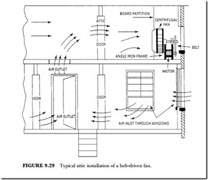
Another installation is shown in Figure 9.29. This fan is a centrifugal curved-blade type, mounted on a light angle-iron frame, which supports the fan wheel, shaft, and bearings. The air inlet in this installation is placed close to a circular opening, which is cut in an airtight board partition that serves to divide the attic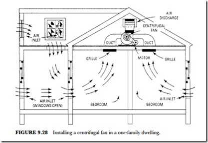
space into a suction and discharge chamber. The air is admitted through open windows and doors and is then drawn up the attic stairway through the fan into the discharge chamber.
The routine of operation to secure the best and most efficient results with an attic fan is important. A typ- ical operating routine might require that, in the late afternoon when the outdoor temperature begins to fall, the windows on the first floor and the grilles in the ceiling or the attic floor be opened and the second-floor windows kept closed. This will place the principal cooling effect in the living rooms. Shortly before bedtime,
the first-floor windows may be closed and those on the second floor opened to transfer the cooling effect to the bedrooms. A suitable time clock may be used to shut the motor off before arising time.
Ventilation Methods
Ventilation is produced by two basic methods: natural and mechanical. Open windows, vents, or drafts obtain natural ventilation, whereas mechanical ventilation is produced by the use of fans.
Thermal effect is possibly better known as flue effect. Flue effect is the draft in a stack or chimney that is produced within a building when the outdoor temperature is lower than the indoor temperature. This is caused by the difference in weight of the warm column of air within the building and the cooler air outside.
Air may be filtered two ways: dry filtering and wet filtering. Various air-cleaning equipment (such as filtering, washing, or combined filtering and washing devices) is used to purify the air. When designing the duct network, ample filter area must be included so that the air velocity passing through the filters is sufficient. Accuracy in estimating the resistance to the flow of air through the duct system is important in the se- lection of blower motors. Resistance should be kept as low as possible in the interest of economy. Ducts should be installed as short as possible.
Competent medical authorities have properly emphasized the effect of dust on health. Air-conditioning apparatus removes these contaminants from the air. The apparatus also provides the correct amount of moisture so that the respiratory tracts are not dehydrated but are kept properly moist. Dust is more than just dry dirt. It is a complex, variable mixture of materials and, as a whole, is rather uninviting, especially the type found in and around human habitation. Dust contains fine particles of sand, soot, earth, rust, fiber, animal and vegetable refuse, hair, and chemicals.
