Examples: Open System Devices
Reversible Turbine with Kinetic Energy
Steam (water vapor) at 15 MPa, 500 ◦C is expanded in a steady state adiabatic reversible turbine to 40 kPa. The inlet diameter of the turbine is d1 = 0.1 m, the exit diameter is d2 = 1.0 m, and the entry velocity is V1 = 40 m . We determine the properties of the end state and the power produced. As we do this, we consider the question whether the kinetic energy of the flow can be ignored.
From the steam table for water we find specific volume, enthalpy and entropy of the inlet state as
The corresponding values for volume and enthalpy are
is far smaller than the contribution of thermal energy (h1 − h2s). This example supports our statement that in the computation of turbines and compressors kinetic energy can be ignored.
The power produced by the reversible turbine is
Irreversible Turbine
We consider the turbine of the previous example for the irreversible case, with an isentropic efficiency of ηT = 0.8. The T-s-diagram for the turbine is depicted as process (1 − 2) in Fig. 9.10.
Due to the definition of isentropic efficiency, the specific work and the power produced for this turbine is
Irreversible Compressor
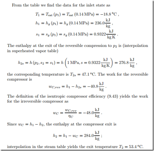
In a refrigeration cycle, cooling fluid R134a enters the adiabatic compressor as saturated vapor at p1 = 0.14 MPa. The compressor with isentropic effi- ciency of ηC = 0.85 compresses the vapor to p2 = 1 MPa. We compute the specific work required. The irreversible compression process (1 − 2), and the reversible ideal process (1 − 2s) are indicated in the T-s-diagram of Fig. 9.11.
Irreversible Pump
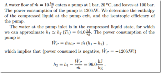
Considering water as incompressible liquid with v1 ‘"" vf (T1) = 0.001 m , we have for a reversible pump between the two pressures
Isobaric Evaporation
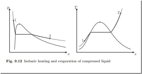
![]() A mass flow of 36 t compressed water at 25 ◦C, 80 bar is isobarically heated and evaporated to 550 ◦C. The heat is provided from combustion of coal which delivers qcoal = 20 MJ of heat per kg of coal. We determine the mass flow of coal required for this process. Figure 9.12 shows the process diagrams.
A mass flow of 36 t compressed water at 25 ◦C, 80 bar is isobarically heated and evaporated to 550 ◦C. The heat is provided from combustion of coal which delivers qcoal = 20 MJ of heat per kg of coal. We determine the mass flow of coal required for this process. Figure 9.12 shows the process diagrams.
With the enthalpies of water
We further assume that the heat generated by combustion of coal provides a hot environment (the boiler) at temperature TB = 1100 K. The entropies of in- and outflow are
Throttling of Compressed Liquid
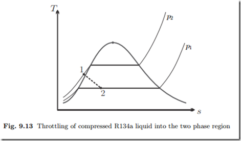
Cooling fluid R134a at T1 = 16 ◦C, p1 = 0.8 MPa, runs through an adiabatic throttle, which it leaves at p2 = 140 kPa. We determine the exit state of the flow.
Since the saturation pressure psat (T1) = 0.504 MPa is less than the actual pressure p1, the initial state is compressed liquid. The throttle is isenthalpic, that is h2 = h1. With the approximation for compressed liquid, we have for the latter
Nozzle
Argon at T1 = 600 K, p1 = 15 bar enters an adiabatic nozzle in which it is expanded to p2 = 150 kPa. The nozzle efficiency is 92%. We determine the maximum possible exit velocity, the actual exit velocity and the exit temperature.
Diffuser
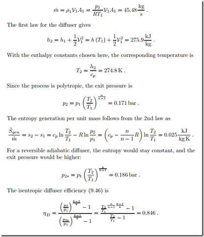
Air enters the adiabatic irreversible diffuser of an air engine with a velocity of V1 = 300 m , at p1 = 0.1 bar, T1 = 230 K. The inlet cross section is A1 = 1 m2.
The process can be described as polytropic with n = 1.5. We determine the pressure at the end of the diffuser, where the flow velocity can be ignored (V2 ‘"" 0), and the mass flow.
Throughout the process the temperature is so low that constant specific heats can be assumed. We set the enthalpy constants such that h = cpT where cp = 1.004 kJ and T is the temperature in Kelvin.
The mass flow into the diffuser is


