OPERATION OF THE UNIT
The flow of refrigerant through the TOTALCLAIM system is determined by the mode or submode in which the unit is operating. The state of the refrigerant at various points in the refrigerant cycle is deter- mined by the mode or submode. A key to understanding the system is to know that the storage cylinder plays an important role in the refrigerant cycle. It sometimes acts as a collector, sometimes as an evaporator, other times as a condenser, and still other times as an ambient-temperature charging bottle. Another key to understanding the system is knowing when the various solenoid valves are open and closed. This information is provided in Table 12.1, which should be used in conjunction with the mode descriptions that follow.
Figure 12.6 shows the arrangement of refrigeration-cycle components in the TOTALCLAIM system. In a normal recovery operation, the unit will extract liquid refrigerant first. Table 12.1 shows that SV-7 is open and SV-3 is closed during liquid recovery. These conditions would exist if the operator selected the “LIQ- UID” option at the keyboard.
Given the solenoid-valve conditions shown, liquid at about ambient temperature is extracted from the tar- get system and flows into the storage cylinder. Low-pressure, low-temperature gas is drawn from the cylinder through SV-1. The high-temperature, high-pressure gas leaving the compressor discharge is condensed to a high-temperature, high-pressure liquid. Note that SV-4 is closed in liquid-recovery mode, while in vapor recovery mode it is open. With SV-4 closed, the refrigerant flows through the expansion device. Because of the pressure drop, the refrigerant returns to the storage cylinder as a low-temperature, low-pressure liquid/vapor mixture. This process cools the storage cylinder. In the recovery plus and recovery modes, the system will automatically enter a storage “cylinder cooling” cycle after 2 minutes of liquid recovery. Stor- age-cylinder cooling is described later.
When R-22 or R-502 is being processed, the microprocessor will open SV-4, which acts as a parallel expansion device for these refrigerants at higher ambient temperatures.
In vapor-recovery operations, the flow is changed significantly, as shown in Figure 12.6. SV-7 and SV-1 are closed and SV-3 is open, bypassing the storage cylinder. Therefore, ambient temperature, low-pressure vapor extracted from the target system is pulled directly into the TOTALCLAIM unit. The other signifi- cant difference from liquid-recovery operations is that SV-4 is open. Thus, the relatively high-temperature, high-pressure liquid leaving the condenser will enter the storage cylinder in that state.
In the recovery mode, one complete recovery cycle is performed. The cycle ends when the pressure in the system being evacuated reaches 0 psig or below.
In the recovery-plus mode, multiple recovery cycles are performed. Refrigerant is extracted as shown in Figures 12.6 and 12.7. First it is liquid, then vapor, unless vapor recovery is selected at the control panel. During both the liquid and vapor recovery cycles, storage-cylinder cooling will be initiated as determined by time, temperature, and/or pressure conditions.
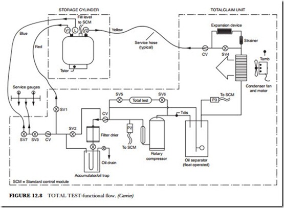
If TOTALTEST is selected (Figure 12.8), the microprocessor will open SV-5 and SV-6 for 1 to 4 min- utes, depending on the refrigerant type, at the end of the recovery or recycle operation. The refrigerant will be sampled during that period.
Storage Cylinder Cooling
Low-suction pressures are created at the TOTALCLAIM compressor. As the target system approaches a vacuum, it causes reduced refrigerant flow. This, in turn, causes high temperatures that would eventually damage the TOTALCLAIM compressor.
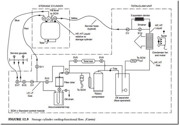
To avoid compressor damage, the microprocessor automatically switches TOTALCLAIM into the “stor- age cylinder cooling” submode as needed to maintain proper cooling of the compressor. In this submode, connections to the target unit are closed and SV-1 is opened. (See Figure 12.9 and Table 12.1.) Now the TOTALCLAIM functions in a closed loop, SV-4 is closed, placing the capillary-tube expansion device in the loop. The storage cylinder now acts as a flooded evaporator to cool the refrigerant. The cooling period lasts from 90 seconds to 15 minutes, depending on the recovery mode and the state of the refrigerant being processed (liquid or vapor). Over a period of 10 to 15 minutes, the cylinder temperature is reduced from 60 to 70 degrees F (15.6-21.1 degrees C) below surrounding ambient temperature. Thus, during subsequent re- covery cycles, the storage cylinder acts as a low-temperature condenser in addition to the higher-tempera- ture air-cooled condenser.
Recycle Operation
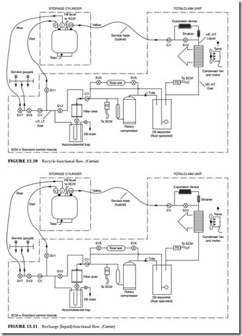
In the recycle mode, shown in Figure 12.10, the microprocessor closes SV-3 and SV-7 and opens SV-1. Un- der those conditions, refrigerant vapor is drawn from the storage cylinder and cycled through the TOTAL- CLAIM unit to remove additional contaminants. The operator sets the recycle time at the control panel and
the microprocessor stops the cycle at the end of that time. If the operator does not select a run time, a de- fault time of 1 hour is automatically selected.
Recharge Operation
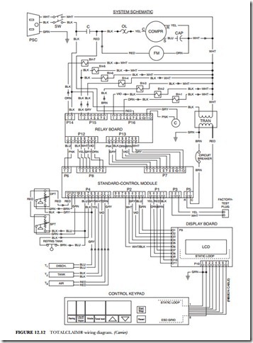
In the recharge mode, shown in Figure 12.11, TOTALCLAIM is basically a charging cylinder. All solenoid valves except SV-7 are closed. The compressor and condenser fan are turned off. The target unit draws liquid refrigerant from the TOTALCLAIM storage cylinder. In applications where vapor recharging is required, the blue hose must be moved from valve L (blue-handled) to valve V1 (red-handled) on the storage cylinder.
Service Operation
The service mode is selected when it is necessary to evacuate the TOTALCLAIM system. The compressor and condenser fan are shut off, and all solenoid valves, except SV-5, SV-6, and SV-7, are open to permit refrigerant to be drawn from the TOTALCLAIM system.
Test Operation
The test mode permits the technician to energize individual solenoid valves in order to simplify trou- bleshooting of the control circuits. This mode is selected by pressing the RESET and MODE keys for 5 seconds. The test mode takes priority over all other modes. When the test mode is turned on, all solenoids are deenergized. Then, using the arrow keys, the technician can energize individual solenoids and trace the en- ergizing signal along the path. If there is a malfunction in the path, it can be isolated to the solenoid valve,
relay module, or standard control module (SCM). SV-5 and SV-6 are energized at the same time. All the others are operated individually. The START/STOP key is used to exit the test mode.
Control Circuits
The compressor and fan both operate from 115-volt single-phase power. The contactor, C, which is ener- gized by the SCM, controls both components. The relay is energized under the “compressor/condenser fan on” conditions shown in Table 12.1. An external overload device disables the compressor in the event of a current overload or excessively high temperature. The device will reset automatically when internal temper- ature drops to a safe level (see Figure 12.12).
The SCM receives data from several sources within the unit. Temperature data is supplied by thermis- tors located in the compressor discharge (TDIS), the storage cylinder (TSTOR), and the ambient-air intake (TAMB). These are identified as T1, T2, and T3 on the schematic diagram. The unit will shut down, and an error code will appear on the display if any of these thermistors fail, either open or shorted.
Error Code Thermistor
E03 Ambient air
E04 Compressor discharge E05 Storage cylinder
A level-sensing device inside the storage cylinder allows the SCM to monitor the contents of the tank. When the tank reaches 80 percent full, 50 pounds or 22.7 kg, the SCM will stop the recovery process, and error code E09 will appear on the display.
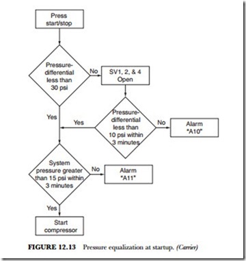
The SCM monitors suction and discharge pressures from the pressure transducers, SPT and DPT re- spectively. In the refrigerant-flow diagram (Figures 12.6 through 12.11) they are designated as P2 and P3, respectively. The SCM will not allow the compressor to start unless the pressures in the unit reach the correct levels within 3 minutes of starting. The flow chart in Figure 12.13 shows the sequencing of this process. If the pressure differential is greater than 30 psi, the SCM will energize SV-1, SV-2, and SV-4 to allow the pressures to equalize. The probable causes of an A11 alarm are storage-cylinder refrigerant hoses not being connected, storage-cylinder valves not being open, or service manifold valves or target unit valves being closed.
The SCM prevents overloads by sequencing its outputs one at a time. This is known as a soft start. Once the START button is pressed, the selected solenoid valves will cycle on or off in their numerical sequence (SV-1, SV-2, and so forth) at no less than 1-second intervals. The compressor and condenser fan are sequenced on after all the selected solenoid valves have been energized or deenergized.
The solenoid valves and contactor (C) are controlled by the SCM through relays on the relay board. Dis- play functions are controlled by the SCM through the display board.
