CIRCUIT BREAKERS
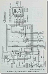
Some electric furnaces are equipped with circuit breakers and a terminal board. The wiring diagram for the Coleman 25 kW electric furnace illustrated in Fig. 10 indicates that both the ter minal board and circuit breakers are located in the power supply feed line to the furnace.
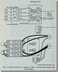
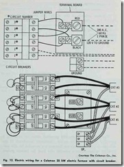
When it is desirable to run branch circuits to the circuit breakers (bypassing the terminal board), the jumper wires be tween the circuit breakers and the wiring is connected as shown in Figs. 11 and 12.
TRANSFORMER
A control voltage transformer is used to limit the amount of output current. Limiting the amount of output current permits the use of open type control wiring.
THERMAL OVERLOAD PROTECTOR
The fan motor is protected against locked rotor or overheated conditions by thermal overload devices. When these conditions occur, the fan motor circuit is automatically opened and the motor is shut off.
ELECTRICAL WIRING
All internal furnace wiring is done at the factory before it is shipped. At the site, the following two types of electrical con nections are required to field wire the unit:
1. Line voltage field wiring.
2. Control voltage field wiring.
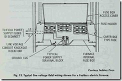
A typical example of line voltage field wumg is shown in Fig. 13. Line voltage wiring involves the connection of the furnace to the building power supply. Line voltage wiring runs directly from the building power panel to a fused disconnect switch. From there, the wiring runs to terminals L1 and L2 on the power supply terminal block.
The unit must be properly grounded either by attaching a grounded conduit for the supply conductors (knockouts in the side panels of Fedders electric furnaces are provided for this pur pose) or by connecting a separate wire from the furnace ground lug to a suitable ground.
The external control voltage circuitry consists of the wiring between the thermostat and the low voltage terminal block located in the control voltage section of the furnace. Instructions for con trol voltage wiring are generally shipped with the thermostat.
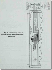
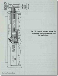
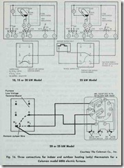
Some typical examples of control voltage field wiring used with Fedders electric furnaces are shown in Figs. 14 and 15. Control voltage field wtrmg connections used with Coleman electricfurnaces are shown in Fig. 16.
The National Electric Code requires that furnaces larger than 10 kW be supplied with branch circuit fusing. Power connections on units of this size are usually made to lugs on the fuse blocks.
