Electric-Fired Furnaces
Electric heating is the only heat that is produced almost as fast as the thermostat calls for it. It is almost instantaneous, because there are no heat exchangers to warm up. The heating elements start producing heat the moment the thermostat calls for it.
Because there is no flame with electric heat, there is no need to vent smoke or flue gases to the outside. Furthermore, there is no chimney loss with electric heat. It is 100% efficient, compared with an efficiency of 80% in furnaces using other fuels.
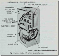
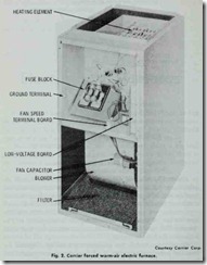
Electric-fired furnaces are available in upflow, downflow, or horizontal flow models, and in a wide range of sizes. For example, Carrier electric furnaces are available in 15 standard models from 5 to 35 kW in 5 kW increments. Other manufacturers offer a similar range of models (Figs. 1 and 2).
An electric-fired furnace should be listed by the Underwriters’ Laboratories for construction and operating safety. Furnaces ap proved by the agency are marked UL Approved.
Electric-fired furnaces should be installed in accordance with local codes and regulations; The National Electrical Code; and recommendations made by The National Fire Protection Association.
ELECTRICAL POWER SUPPLY
Contact the local power company and make certain adequate electrical service is available for the furnace load plus all other appliances that will be on the line.
Check The National Electrical Code and the local code re quirements. All wiring (including sizing) must comply with the requirements of these codes. When there is any conflict, the local codes and regulations will take precedence. The manufacturer’s requirements are also important. For example, Janitrol discour ages the use of aluminum wire although it is acceptable to The National Electrical Code. Use of aluminum wire in this case could jeopardize the furnace warranty.
Be sure to consult the manufacturer’s wiring diagrams for electrical power requirements. Read the instructions carefully and be sure you understand them thoroughly before you begin work.
PLANNING SUGGESTIONS
If an electric-fired furnace is being planned for a new struc ture, the maximum heat loss for each heated space must be calcu lated in accordance with procedures described in the manuals of the National Warm Air Heating & Air Conditioning Association or by a comparable method. This is very important because this data will be used to determine the size (capacity) of the furnace selected for the installation.
Do not consider an electric heating system unless the structure is properly insulated. This type of insulating will be more exten sive than that used with other types of heating systems. For exam ple, ceilings should have a minimum of 6 inches of blanket or loose type insulation, and cavities between studs in exterior walls should be completely filled with insulation. A description of the insulation requirements for a structure in which an electric heat ing system is used is included in Chapter 9 (ELECTRIC HEAT lNG SYSTEMS).
If the heating or heating/cooling installation is to be approved by either the FHA or VA, heat loss and heat gain calculations should be made in accordance with the procedures described in National Environmental Systems Contractors Manual J.
Location and Clearance
An electric-fired forced warm-air furnace should be located as near as possible to the center of the heat distribution system. Centralizing the furnace eliminates the need for one or more exceptionally long supply ducts. Long supply ducts are uneco nomical because they are subject to a certain amount of heat loss. The number of elbows should be kept to a minimum for the same reason.
Electric furnaces are not vented because electric heat is not produced by the combustion process. No flue gases or other toxic products of the combustion process occur with electric heat. As a result, a chimney and flue pipe are not required and it is not nec essary to consider these factors when locating the furnace.
A clearance of 24-30 inches in front of the furnace access panel should be provided for servicing and repairs. There is no minimum clearance requirement for ductwork and combustible materials. Electric furnaces may be installed with zero clearance between the cabinet and combustible materials, because the heat from the furnace is not produced by a flame.
INSTALLATION RECOMMENDATIONS
New electric furnaces for residential installation are shipped from the factory with all internal wiring completed. These fur naces are also generally shipped as a preassembled unit. In order to install the new furnace, the electric service from the line volt age main and the low voltage thermostat must be connected. Directions for making these connections are found in the furnace manufacturer’s installation instructions.
Familiarize yourself with all local codes and regulations which govern the installation of an electric-fired furnace. Local codes and regulations take precedence over national standards.
Check the insulation of the structure to determine if it is pro perly insulated for electric heat. The insulation should be installed in accordance with recommendations in “All Weather Comfort Standard of Electrically Heated and Air Conditioned Homes” (Electric Heating Association).
The furnace should be mounted on a level surface. If the unit is not level, it may develop serious vibrations. An insulating ma terial can be placed under the furnace in most installations to reduce sound vibrations when the unit is operating. A noncom bustible base is recommended for counterflow models.
Duct Connections
Detailed information concerning the installation of an air duct system is contained in the following two publications of the National Fire Protection Association:
1. “Installation of Air Conditioning and Ventilating Sys tems of Other Than Residence Type” (NFPA No. 90A).
2. “Residence Type Warm Air Heating and Air Condition ing Systems” (NFPA No. 90B).
Additional information about duct connections can be found in Chapter 7, Volume 2 (DUCTS AND DUCT SYSTEMS). The comments made in Chapter 11 (GAS-FIRED FURNACES) about furnace duct connections and air distribution ducts apply for the most part to ducts used with electric-fired forced warm-air furnaces.
BASIC COMPONENTS
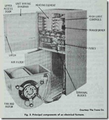
An electric-fired forced warm-air furnace will generally con sist of the following basic components (Fig. 3):
1. Automatic controls,
2. Safety controls,
3. Heating elements,
4. Blower and motor,
5. Air filter(s).
Each of these components is described in the sections that follow. Additional information is contained in Chapter 10 (FUR NACE FUNDAMENTALS) and the various chapters in which furnace controls are described.


