Electric Duct Heaters
Electric duct heaters are designed and manufactured to function in the same manner as oil- or gas-fired duct furnaces. These are prewired faactory-assembled units available in a wide range of sizes and heating capacities for a variety of different installations.
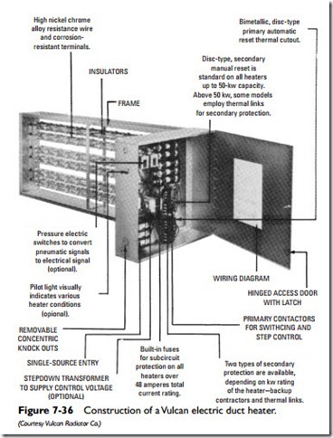
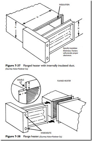
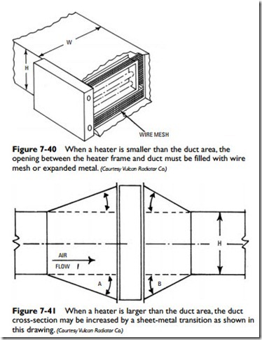
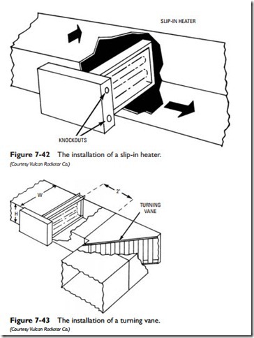
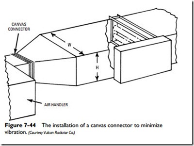
Typical duct heater construction is illustrated by the Vulcan unit in Figure 7-36. The frame for the electric resistors is designed for insertion into the duct as shown in Figures 7-37 through 7-44. These Vulcan duct heaters are available in five standard supply voltage ratings (120, 277 single-phase; 208, 240, and 480 single- or three-phase) or a specific voltage depending on the requirements of the installation.
The control housing is located on the outside of the duct and should be located so that the control panel is accessible for inspection and service. Various standard and optional built-in control compo- nents are available, including (1) staging contactors, (2) control
heat limiters (thermal links). The function of each of these limit controls is to shut off the duct heater when there is no air or when the airflow is too low for efficient operation.
The primary automatic reset, a high-limit control, is a snap- action device that is sensitive to both radiant and convected heat. It is designed to deenergize the duct heater at a preselected, higher- than-normal temperature and to automatically reenergize the unit when it cools.
The secondary manual reset control is a warning device set to open at a temperature higher than the primary reset. It cannot be reset until the heater has cooled below the setpoint, and it must be reset manually.
The heat limiters (thermal links) belong to the secondary protection system. These are fusible, one-time protective devices that must be replaced in the event that they cut out.
Duct heater circuits may be subdivided into equal or unequal heating increments or stages in order to more closely match heater output with temperature variations.
