The condenser is a heat-transfer device. It is used to remove heat from hot refrigerant vapor. Using some method of cooling, the condenser changes the vapor to a liquid. There are three basic methods of cooling the condenser’s hot gases. The method used to cool the refrigerant and return it to the liquid state serves to categorize the two types of condensers: air-cooled and water-cooled. Cooling towers are also used to cool the refrigerant.
Most commercial or residential home air-conditioning units are air-cooled. Water is also used to cool the refrigerant. This is usually done if there is an adequate supply of fairly clean water. Industrial applications rely upon water to cool the condenser gases. The evaporative process is also used to return the condenser gases to the liquid state. Cooling towers use the evaporative process.
CONDENSERS
Air-Cooled Condensers
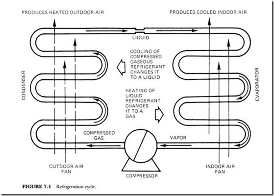
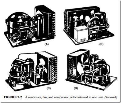
Figure 7.1 illustrates the refrigeration process within an air-cooled condenser. Figure 7.2 shows some of the various types of compressors and condensers mounted as a unit. These units may be located outside the cooled space. Such a location makes it possible to exhaust the heated air from the cooled space. Note that the condenser has a large-bladed fan that pushes air through the condenser fins. The fins are attached to coils of copper or aluminum tubing. The tubing houses the liquid and the gaseous vapors. When the blown air contacts the fins, it cools them. The heat from the compressed gas in the tubing is thus transferred to the cooler fin.
Heat given up by the refrigerant vapor to the condensing medium includes both the heat absorbed in the evaporator and the heat of compression. Thus, the condenser always has a load that is the sum of these two heats. This means that the compressor must handle more heat than that generated by the evaporator. The quantity of heat (in Btu) given off by the condenser is rated in heat per minute per ton of evaporator capacity. These condensers are rated at various suction and condensing temperatures.
The larger the condenser area exposed to the moving airstream, the lower the temperature of the refrigerant when it leaves the condenser. The temperature of the air leaving the vicinity of the condenser will vary with the load inside the area being cooled. If the evaporator picks up the additional heat and transfers it to the condenser, the condenser must transmit this heat to the air passing over the surface of the fins. The temperature rise in the condensing medium passing through the condenser is directly proportional to the con- denser load. It is inversely proportional to the quantity and specific heat of the condensing medium.
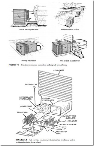
To exhaust the heat without causing the area being cooled to heat up again, it is common practice to locate the condenser outside of the area being conditioned. For example, for an air-conditioned building, the condenser is located on the rooftop or on an outside slab at grade level. (See Figure 7.3.)
Some condensers are cooled by natural airflow. This is the case for domestic refrigerators. Such natural convection condensers use either plate surface or finned tubing. (See Figure 7.4.)
Air-cooled condensers that use fans are classified as chassis-mounted and remote. The chassis-mounted type is shown in Figure 7.2. The compressor, fan, and condenser are mounted as one unit. The remote type is shown in Figure 7.3. Remote air-cooled condensers can be obtained in sizes that range from 1 to 100 tons. The chassis-mounted type is usually limited to 1 ton or less.
Water-Cooled Condensers
Water is used to cool condensers. One method is to cool them with water from the city water supply and then exhaust the water into the sewer. This method can be expensive and in some instances is not allowed by law. When there is a sewer problem, a limited sewer-treatment-plant capacity, or drought, it is impractical to use this cooling method.
The use of recirculation to cool the water for reuse is more practical. However, in recirculation, the power required to pump the water to the cooling location is part of the expense of operating the unit.
There are three types of water-cooled condensers:
• Double-tube
• Shell and coil
• Shell and tube
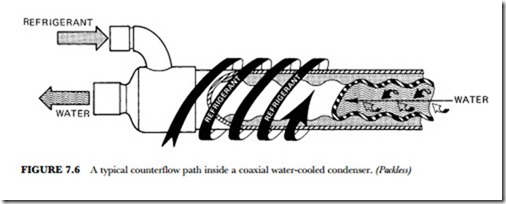
The double-tube type consists of two tubes, one inside the other (see Figure 7.5). Water is piped through the inner tube. Refrigerant is piped through the tube that encloses the inner tube. The refrigerant flows in the opposite direction from the water (see Figure 7.6).
This type of coaxial water-cooled condenser is designed for use with refrigeration and air-conditioning con- densing units where space is limited. These condensers can be mounted vertically, horizontally, or at any angle.
This type of condenser can also be used with cooling towers. It performs at peak heat of rejection with a water-pressure drop of not more than five pounds per square inch, utilizing flow rates of three gallons per minute per ton.
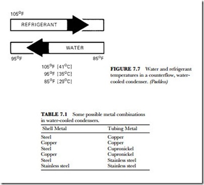
The typical counterflow path shows the refrigerant going in at 105 degrees F (41 degrees C) and the wa- ter at 85 degrees F (30 degrees C) and leaving at 95 degrees F (35 degrees C) (see Figure 7.7).
The counterswirl design, shown in Figure 7.6, gives heat-transfer performance of superior quality. The tube construction provides for excellent mechanical stability. The water-flow path is turbulent. This pro- vides a scrubbing action that maintains cleaner surfaces. The construction method shown also has very high system pressure resistance.
The water-cooled condenser shown in Figure 7.5 can be obtained in a number of combinations. Some of these combinations are listed in Table 7.1. Copper tubing is suggested for use with fresh water and with cool- ing towers. The use of cupronickel is suggested when salt water is used for cooling purposes.
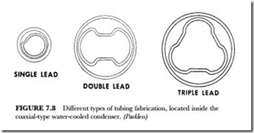
Convolutions to the water tube result in a spinning, swirling water flow that inhibits the accumulation of deposits on the inside of the tube. This contributes to the antifouling characteristics in this type of condenser. Figure 7.8 shows the various types of construction.
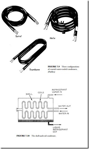
This type of condenser may be added as a booster to standard air-cooled units. Figure 7.9 shows some of the configurations of this type of condenser—the spiral, helix, and trombone. Note the input for the water and for the refrigerant. Using a cooling tower to furnish water to contact the outside tube can further cool the condensers. A water tower can also be used to cool the water sent through the inside tube for cooling purposes. This type of’ condenser is usable where refrigeration or air-conditioning requirements are 1/3 to 3 tons.
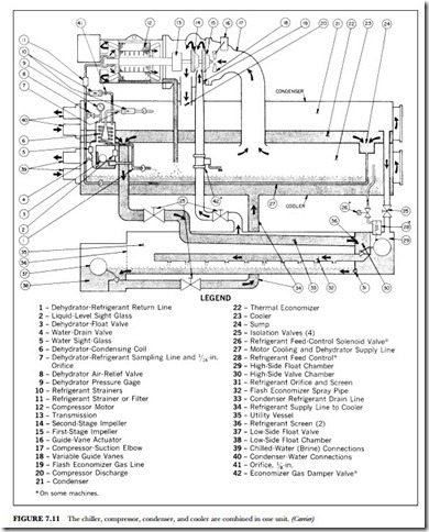
Placing a bare or finned tube inside a steel shell makes the shell-and-coil condenser (see Figure 7.10). Water circulates through the coils. Refrigerant vapor is injected into the shell. The hot vapor contacts the cooler tubes and condenses. The condensed vapor drains from the coils and drops to the bottom of the tank or shell. From there it is recirculated through the refrigerated area by way of the evaporator. In most cases, placing chemicals into the water cleans the unit. The chemicals have a tendency to remove the deposits that build up on the tubing walls.
