CHILLERS
A chiller is part of a condenser. Chillers are used to cool water or brine solutions. The cooled (chilled) water or brine is then fed through pipes to evaporators. This cools the area in which the evaporators are located. This type of cooling, using chilled water or brine, can be used in large air-conditioning units. It can also be used for industrial processes where cooling is required for a particular operation.
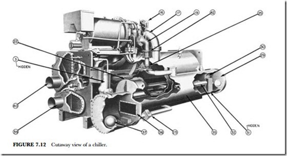
Figure 7.11 illustrates such an operation. Note how the compressor sits atop the condenser. Chillers are the answer to requirements of 200 to 1,600 tons of refrigeration. They are used for process cooling, comfort air conditioning, and nuclear-power-plant cooling. In some cases they are used to provide ice for skating rinks. The arrows in Figure 7.11 indicate the refrigerant flow and the water or brine flow through the large pipes. Figure 7.12 shows the machine in a cutaway view. The following explanation of the various cycles will provide a better understanding of the operation of this type of equipment.
Refrigeration Cycle
The machine compressor continuously draws large quantities of refrigerant vapor from the cooler at a rate determined by the size of the guide vane opening. This compressor suction reduces the pressure within the cooler, allowing the liquid refrigerant to boil vigorously at a fairly low temperature, typically 30 to 35 degrees F (-1 to 2 degrees C).
Liquid refrigerant obtains the energy needed for the change to vapor by removing heat from the water in the cooler tubes. The cold water can then be used in the air-conditioning process.
After removing heat from the water, the refrigerant vapor enters the first stage of the compressor. There it is compressed and flows into the second stage of the compressor, where it is mixed with flash-economizer gas and further compressed.
Compression raises the refrigerant temperature above that of the water flowing through the condenser tubes. When the warm (typically 100 to 105 degrees F [38 to 41 degrees C]) refrigerant vapor contacts the condenser tubes, the relatively cool condensing water (typically 85 to 95 degrees F [29 to 35 degrees C]) re- moves some of the heat and the vapor condenses into a liquid.
Further heat removal occurs in the group of condenser tubes that forms the thermal economizer. Here, the condensed liquid refrigerant is subcooled by contact with the coolest condenser tubes. These are the tubes that contain the entering water.
The subcooled liquid refrigerant drains into a high-side valve chamber. This chamber maintains the proper fluid level in the thermal economizer and meters the refrigerant liquid into a flash economizer chamber. Pressure in this chamber is intermediate between condenser and cooler pressures. At this lower pressure some of the liquid refrigerant flashes to gas, cooling the remaining liquid. The flash gas, having absorbed heat, is returned directly to the compressor’s second stage. Here, it is mixed with gas already compressed by the first-stage impeller. Since the flash gas must pass through only half the compression cy- cle to reach condenser pressure, there is a savings in power.
The cooled liquid refrigerant in the economizer is metered through the low-side valve chamber into the cooler. Because pressure in the cooler is lower than economizer pressure, some of the liquid flashes and cools the remainder to evaporator (cooler) temperature. The cycle is now complete.
Motor Cooling Cycle
Refrigerant liquid from a sump in the condenser (No. 24 in Figure 7.11) is subcooled by passage through a line in the cooler (No. 27 in Figure 7.11). The refrigerant then flows externally through a strainer and variable orifice (No. 11 in Figure 7.11) and enters the compressor motor end. Here, it sprays and cools the compressor rotor and stator. It then collects in the base of the motor casing. Here, it drains into the cooler. Differential pressure between the condenser and cooler maintains the refrigerant flow.
Dehydrator Cycle
The dehydrator removes water and noncondensable gases. It indicates any water leakage into the refrigerant. (See No. 6 in Figure 7.11.)
This system includes a refrigerant condensing coil and chamber, water-drain valve, purging valve, pressure gauge, refrigerant float valve, and refrigerant piping.
A dehydrator sampling line continuously picks up refrigerant vapor and contaminants, if any, from the condenser. Vapor is condensed into a liquid by the dehydrator-condensing coil. Water, if present, separates and floats on the refrigerant liquid. The water level can be observed through a sight glass.
Water may be withdrawn manually at the water drain valve. Air and other non-condensable gases collect in the upper portion of the dehydrator-condensing chamber. The dehydrator gauge indicates the presence of air or other gases through a rise in pressure. These gases may be manually vented through the purging valve.
A float valve maintains the refrigerant liquid level and pressure difference necessary for the refrigerant condensing action. Purified refrigerant is returned to the cooler from the dehydrator float chamber.
Lubrication Cycle
The oil pump and oil reservoir are contained within the uni-shell. Oil is pumped through an oil filter-cooler that removes heat and foreign particles. A portion of the oil is then fed to the compressor motor-end bear- ings and seal. The remaining oil lubricates the compressor transmission, compressor thrust and journal bearings, and seal. Oil is then returned to the reservoir to complete the cycle.
Controls
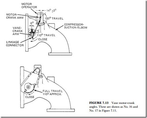
The cooling capacity of the machine is automatically adjusted to match the cooling load by changes in the position of the compressor inlet guide vanes. (See Figure 7.13.)
A temperature-sensing device in the circuit of the chilled water leaving the machine cooler continuously transmits signals to a solid-state module in the machine control center. The module in turn transmits the amplified and modulated temperature signals to an automatic guide vane actuator.
A drop in the temperature of the chilled water leaving the circuit causes the guide vanes to move toward the closed position. This reduces the rate of refrigerant evaporation and vapor flow into the compressor. Ma- chine capacity decreases. A rise in chilled water temperature opens the vanes. More refrigerant vapor moves through the compressor, and the capacity increases.
The modulation of the temperature signals in the control center allows precise control of guide-vane re- sponse regardless of the system load.
Solid-State Capacity Control
In addition to amplifying and modulating the signals from chilled water sensor to vane actuator, the solid- state module in the control center provides a means for preventing the compressor from exceeding full load amperes. It also provides a means for limiting motor current down to 40 percent of full load amperes to re- duce electrical demand rates.
A throttle-adjustment screw eliminates guide-vane hunting. A manual capacity-control knob allows the operator to open, close, or hold the guide-vane position when desired.

