SCHEMATIC DIAGRAMS
Schematic diagrams show components in their electrical sequence without regard for physical location. Schematic diagrams are used to troubleshoot and install control circuits. Schematics are generally easier to read and understand than wiring diagrams.
WIRING DIAGRAMS
Wiring diagrams show components mounted in their general location with connecting wires. A wiring diagram is used to represent how the circuit generally appears. To help illustrate the differences between wiring diagrams and schematics, a basic control circuit will first be explained as a schematic and then shown as a wiring diagram.
READING SCHEMATIC DIAGRAMS
To read a schematic diagram, a few rules must first be learned. Commit the following rules to memory:
1. Reading a schematic diagram is similar to reading a book. It is read from left to right and from top to bottom.
2. Electrical symbols are always shown in their off or deenergized position.
3. Relay contact symbols are shown with the same numbers or letters that are used to designate the relay coil. All contact symbols that have the same number or letter as a coil are controlled by that coil regardless of where in the circuit they are located.
4. When a relay is energized, or turned on, all of its contacts change position. If a contact is shown as normally open, it will close when the coil is energized. If the contact is shown normally closed, it will open when the coil is turned on.
5. There must be a complete circuit before current can flow through a component.
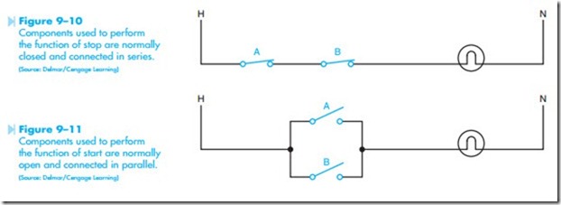
6. Components used to provide a function of stop are generally wired normally closed and connected in series. Figure 9–10 illustrates this concept. Both switches A and B are nor- mally closed and connected in series. If either switch is opened, connection to the lamp will be broken and current will stop flowing in the circuit.
7. Components used to provide the function of start are generally wired normally open and connected in parallel. In Figure 9–11, switches A and B are normally open and connected in parallel with each other. If either switch is closed, a current path will be provided for the lamp and it will turn on.
DASHED LINES
Often the service technician must be able to deter- mine what dashed lines indicate. Schematic diagrams often contain dashed lines.
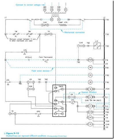
In the schematic diagram shown in Figure 9–12, dashed lines indicate several different conditions.
1. Mechanical connection between two components such as those shown in electrical symbols 5, 8, and 9. Each of these symbols show a dashed line connected between different components. The dashed line indicates that when one component is changed the other one is changed, at the same time. The double-acting push buttons illustrated in number 5 will both operate when one of them is pushed.
2. Field wired or installed components.
3. Components used only in special circumstances.
4. Factory wired or installed components.
At the top of the diagram, dashed lines indicate that only one set of the primary terminals is to be connected depending on the amount of input volt- age. An input voltage of 480 volts, for example, would have one line connected to the H1 terminal and the other to the H4 terminal. An input volt- age of 208 volts would have one line connected to the H1 terminal and the other connected to the H2 terminal.
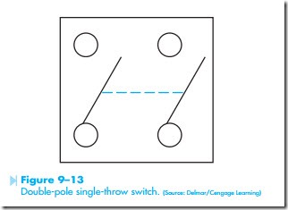
Another dashed line connected between two switches indicates that these two switches are mechanically connected. In reality, this would be a double-pole single-throw switch, Figure 9–13. The dashed line indicates that when one switch is opened or closed, the other one is opened or closed also.
Several components, such as 1M, 2M, and 3M are connected with dashed lines. The dashed lines in this instance indicates that these devices are field wired and not part of the assembled unit. Wiring to these devices is connected during the installation of the equipment. It should be noted that some diagrams will use dashed lines to indicate factory- installed wiring, and solid lines illustrate field- connected devices. There is no hard rule. It is generally necessary for the service person to determine the meaning of the lines on a particular schematic.
Another set of components shown in Figure 9–12 is surrounded by dashed lines. These dashed lines mark components that are used under special circumstances. Contactor coil, C2, and contact CR are installed only if the compressor motor utilizes part winding starting. If the motor does not employ part winding starting, these components will not be present.
EXAMPLE
The first circuit to be discussed is a basic control circuit used throughout industry. Figure 9–14 shows a start-stop push button circuit. This schematic shows both the control circuit and the motor circuit. Schematic diagrams do not always show both control and motor connections. Many schematic diagrams show only the control circuit.
Notice in this schematic that there is no complete circuit to M motor starter coil because of the open start push button and open M auxiliary contacts. There is also no connection to the motor because of the open-M load contacts. The open-M contacts connected in parallel with the start button are small contacts intended to be used as part of the control circuit. This set of contacts is generally referred to as the holding, sealing, or maintaining contacts. These contacts are used to provide a continued circuit to the M coil when the start button is released.
The second set of M contacts is connected in series with the overload heater element and the motor, and are known as load contacts. These contacts are large and designed to carry the cur- rent needed to operate the load. Notice that these contacts are normally open and there is no current path to the motor.
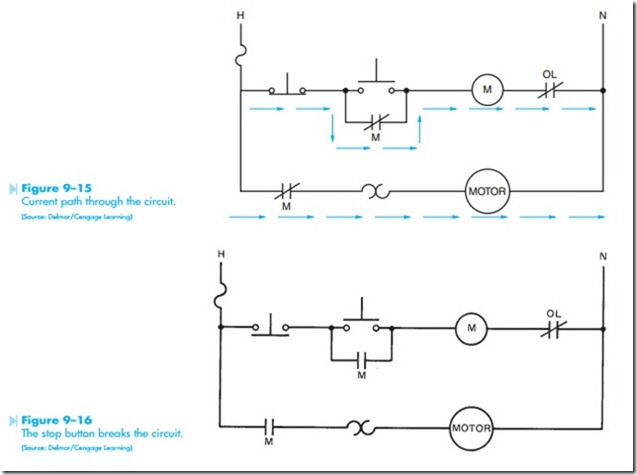
When the start button is pushed, a path for current flow is provided to the M-motor starter coil. When the M coil energizes, both M contacts close, Figure 9–15. The small auxiliary contact provides a continued cur- rent path to the motor starter coil when the start but- ton is released and returns to its open position. The large M load contact closes and provides a complete circuit to the motor and the motor begins to run. The motor will continue to operate in this manner as long as the M coil remains energized.
If the stop button is pushed, Figure 9–16, the current path to the M coil is broken and the coil de-energizes. This causes both M contacts to return to their normally open position. When M holding contacts open, there is no longer a complete circuit provided to the coil when the stop button is returned to its normal position. The circuit remains in the off position until the start button is again pushed.
Notice that the overload contact is connected in series with the motor starter coil. If the overload contact should open, it has the same effect as pressing the stop button. The fuse is connected in series with both the control circuit and the motor. If the fuse should open, it has the effect of disconnecting power from the line.
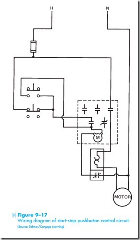
A wiring diagram for the start-stop pushbutton circuit is shown in Figure 9–17. Although this diagram looks completely different, it is electrically the same as the schematic diagram. Notice the push button symbols indicate double-acting push buttons. The stop button, however, uses only the normally closed section and the start button uses only the
normally open section. The motor starter shows three load contacts and two auxiliary contacts. One auxiliary contact is open and one is closed. Notice that only the open contact has been used.
The overload unit shows two different sections. One section contains the thermal heater element connected in series with the motor, and the nor- mally closed contact is connected in series with the coil of the M-motor starter.
EXAMPLE
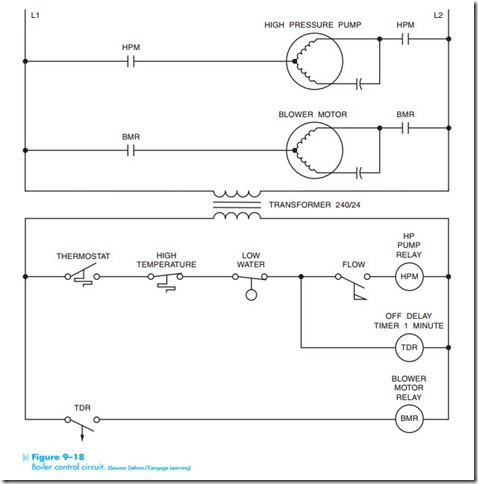
The circuit shown in Figure 9–18 controls the operation of an oil-fired boiler. A high pressure pump motor is used to inject fuel oil into a combustion chamber where it is burned. A blower motor is used to supply combustion air to the chamber. The circuit will not permit fuel oil to be injected into the chamber unless the blower motor is operating. The circuit also permits the blower motor to continue operation for a period of one minute after the thermostat is satisfied. This permits any residual smoke or fumes to be removed from the combustion chamber.
The first step in understanding the operation of the circuit is to examine the components and determine what they control. The thermostat is a normally closed held open switch. It is normally closed because the movable contact is drawn above the stationary contact. The movable contact is not making connection to the stationary contact, however. This indicates that the contact is being held open. The thermal symbol indicates that the contact is controlled by temperature. The thermal symbol represents a bimetal helix. An increase in temperature causes the helix to expand and push upward on the contact. A decrease in temperature causes the helix to contract. If the helix contracts enough, the movable contact will make connection with the stationary contact and close the switch. This thermostat symbol indicates that an increase of temperature will open the switch and a decrease of temperature will close the switch. This is the normal operation of a heating thermostat.
The high temperature switch is a thermally activated switch also. The switch is shown normally closed. If the temperature should increase high enough, the switch will open and break connection to the high pressure pump motor relay and time delay relay.
The low water switch is a normally open held closed switch. The switch is normally open because the movable contact is drawn below the stationary contact. Because the movable contact is touching the station contact it is being held closed. This switch is drawn to indicate that a drop in liquid level will cause the switch contacts to open and break the circuit to the high pressure pump motor relay and time delay relay. One of the most dangerous conditions for a boiler is a low water level. If the water level should drop below a preset point, the switch will open.
The flow switch is normally open. A flow of air causes the switch contacts to close. The flow switch is used to insure that there is a flow of combustion air into the combustion chamber before fuel oil is injected into the chamber.
The time delay contact (TDR) is connected in series with the blower motor relay coil. The symbol indicates that the timer is an off delay timer. The arrow always points in the direction the contacts will move after the delay period. The arrow indicates that the contacts will delay reopening after they have changed position.
Related posts:
Incoming search terms:
- amazon
- chillar circuit diagram
- what is the symbols for normally open and closed thermastats?
- start stop schematic diagram
- relay shematic diagram
- wiring schematic 2003 Tacoma
- reading honeywell 24v/120v single pole relays diagrams
- motor control circuit symbols
- in wiring diagram what does a circle with wavy line mean
- hvac schematic/circuits
- hvac electrical controls and schematics
- cv in electrical schematics -resume
- d341396po1
- wiring diagram for 703041/181-300-23/000 ppressure controller
- charts on how current flow through a start / stop pushbutton
- schematic control
- what is CR symbol in diagrahm
- EC200 crane control box and motor 12 volt schematics
- boss controller relay schematic
- dewert control box circuit
- bercomac controller schematic
- electrical schematic connection for HVAC
- double lines on control wiring diagram
- 6-7 Reading an Schematic diagrams How many schematic symbols are there (excluding the wire)? *
- when looking at a wiring diagram what is the difference between a solid line an a line with a dash
- wiring diagrams for using motor controller US-52
- dotted line with two lines connecting mean on a wiring diagram
- Control circuits
- 3169257-b schmatic diagram
- control circuit of various starting diagram
- a dashed line on an diagram represents quizlet
- CONTROL RELAY LINE NUMBER
- reading schematics wiring diagrams for pump controls
- on eletrical drawing are iputs on rhe bottom of device
- schematic diagrams motor control cad
- picture of one load in electrical line drawing
- A dashed line in a pneumatic schematic diagram represents a(n) _____________ a main line b exhaust line c pilot line d enclosure line
- how to read motor control schematics
- Electrical Control Schematic Symbols
- SOLID CIRCUIT LINE OR DASHED
- control diagram symbols
- electrical control circuit diagram
- motor control schematic diagram
- what is the bold line between AUTOMOTIVE switch contacts in a wiring diagram
- control wiring diagrams
- Select the three best reasons why the Electrical Worker should consult the control diagram for AHU 3
- Electrical machinery mail
- Hydroelectric Machinery AS contact us mail
- Hydroelectric Machinery DAT contact us mail
- with the connecting wire in each switch in the position shown in the diagram ;the lamp is off
