Electrical Wiring
A wiring diagram specifying the electrical connections between the
various controls should be provided by the furnace and stoker manufacturers.
Caution
All electrical wiring must be done in accordance with the National Electrical Code and the local authorized code.
Warning
Turn off the electric power at the circuit breakers (or fuse box) before making any line voltage connections.
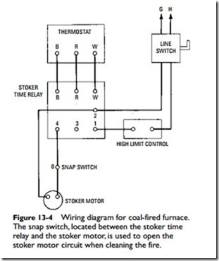
As shown in Figure 13-4, a room thermostat operating through the stoker time relay starts and stops the stoker in response to tem- perature conditions. The time relay operates the stoker to keep the fire alive during periods when heat may not be required by the room thermostat. A stoker time relay should include a device to shut down the stoker immediately after a shutdown call from the thermostat. This action eliminates fuel waste by preventing the overshooting of room temperature.
A high-limit control is used to protect the system against excessive temperatures. This control takes the form of an air switch in a warm-air heating system.
A snap switch should be installed in the wiring between the stoker time relay and the stoker motor to open the stoker motor circuit when the firebox or ashpit is being cleaned (Figure 13-4).
A wiring diagram for a combination wood-oil furnace is shown in Figure 13-5. Note that the wood controls and oil controls are wired as separate systems. A similar method of wiring the controls as two separate systems is used for a combination wood-gas furnace
(Figure 13-6). This is a common practice on furnaces designed to burn more than one fuel.
The wiring diagrams shown in Figures 13-7 and 13-8 are for gas and oil heating systems with air conditioning.
