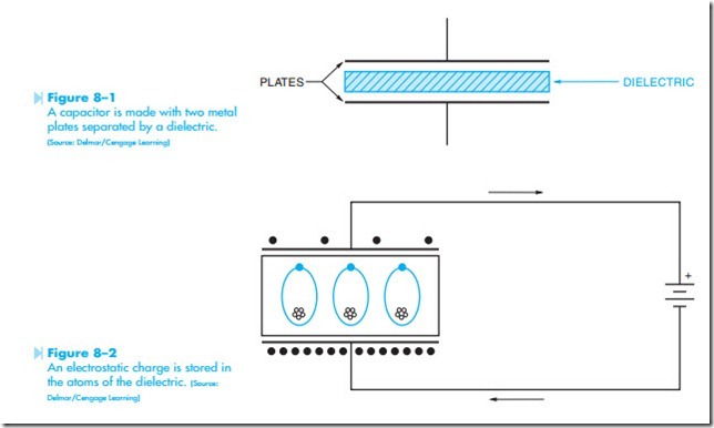
The third type of alternating-current load to be dis- cussed is capacitance. A capacitor can be made by separating two metal plates with an insulating material, Figure 8–1. The insulating material used to isolate the plates from each other is called the dielectric. There are three factors that determine how much capacitance a capacitor will have. These are:
1. The surface area of the plates.
2. The distance between the plates.
3. The type of dielectric material used between the plates.
CHARGING A CAPACITOR
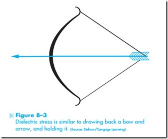
In Figure 8–2, the terminals of a capacitor have been connected to a battery. Electrons are negative particles. Therefore, the positive terminal of
the battery attracts electrons from one plate of the capacitor. The negative terminal of the battery will cause electrons to flow to the other capacitor plate. This flow of current will continue until the voltage across the capacitor plates is equal to the battery voltage. If the battery is disconnected, the capacitor will be left in a charged state. CAUTION: It is the habit of some people to charge a capacitor to a high voltage and then hand the capacitor to another per- son. While some people think this is comical, it is an extremely dangerous practice. Capacitors have the ability to supply an almost infinite amount of current. Under certain conditions, a capacitor can have enough power to cause a person’s heart to go into fibrillation.
ELECTROSTATIC CHARGE
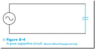
Notice the illustration of the atoms in the dielectric material in Figure 8–2. When a capacitor has been charged, the negative electrons of the dielectric material are repelled from the negative plate of the capacitor and attracted to the positive plate. This causes the electron orbit of the atoms in the dielectric to extend. This places the atoms of the dielectric material in tension. This is known as dielectric stress. Placing the atoms of the dielectric under stress has the same effect as drawing back a bow and arrow and holding it, Figure 8–3.
The amount of dielectric stress is determined by the voltage between the plates. The greater the volt- age, the greater the dielectric stress. If the voltage becomes too great, the dielectric will break down and destroy the capacitor. This is the reason capacitors have a voltage rating that must be followed.
The energy of a capacitor is stored in the dielectric and is known as an electrostatic charge. It is this electrostatic charge that permits the capacitor to produce extremely high currents under certain conditions. If the leads of a charged capacitor are shorted together, it has the same effect as releasing the drawn bow in Figure 8–3. The arrow will be propelled forward at great speed. The same is true for the electrons of the capacitor. When the electron orbits of the dielectric snap back, the electrons stored on the negative capacitor plate are propelled toward the positive plate at great speed.
CAPACITOR RATINGS
Capacitors are rated in units called the farad. The farad is actually such a large amount of capacitance it is not practical to use. For this reason a unit called the micro-farad is generally used. A micro-farad is one millionth of a farad. The Greek lowercase letter mu is used to symbolize micro, μ. The term micro-farad is indicated by combining mu and lowercase f, μf. Because the letter mu is not included on a standard typewriter, the term micro-farad is some- times shown as uf or mf. All of these terms mean the same thing.
Another term used is the pico-farad. This termis used for extremely small capacitors found in electronics applications. A pico-farad is one millionth of a micro-farad and is generally shown as μμf or pf.
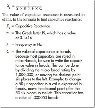
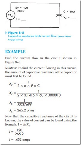
When AC voltage is applied to a capacitor, Figure 8–4, the plates of the capacitor are alternately charged and discharged each time the cur- rent changes direction of flow. When a capacitor is charged, the voltage across its plates becomes the same as this applied voltage. As the voltage across the plates of a capacitor increases, it offers resistance to the flow of current. The applied volt- age must continually overcome the voltage of the capacitor to produce current flow. The current in a pure-capacitive circuit is limited by the
voltage of the charged capacitor. Because current is limited by a counter voltage and not resistance, the counter voltage of the capacitor is referred to as reactance. Recall that the symbol for reactance is X. Because this reactance is caused by capacitance, it is called capacitive reactance and is symbolized by XC (pronounced X sub c).
The amount of capacitive reactance in a circuit is
determined by two factors. These are:
1. Frequency of the AC voltage.
2. The size of the capacitor.
If the frequency of the line and the capacitance rating of the capacitor are known, the capacitive reactance can be found using the following formula:
CURRENT FLOW IN A CAPACITIVE CIRCUIT
Notice that a capacitor is constructed of two metal plates separated by an insulator. One of the metal plates is connected to one side of the circuit, and the other metal plate is connected to the other side of the circuit. Because there is an insulator separating the two plates, current cannot flow through a capacitor. When a capacitor is connected into a direct- current circuit, current will flow until the capacitor has been charged to the value of the applied voltage,
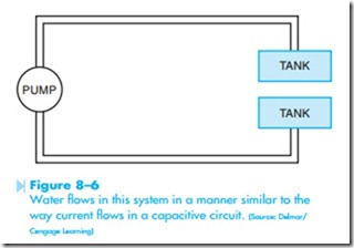
and then stop. When a capacitor is connected into an alternating-current circuit, current will “appear” to flow through the capacitor. This is because the plates of the capacitor are alternately charged and discharged each time the current reverses direction. To understand this concept better, refer to the water circuit shown in Figure 8–6. In this illustration, a water pump is connected to two tanks. The pump is used to pump water back and forth between the two tanks. When one tank becomes full, the direction of the pump is reversed and water is pumped from the full tank back into the empty tank. Notice that there is no complete loop in this hydraulic circuit for water to flow from one side of the pump to the other, but water does flow because it is continuously pumped from one tank to the other.
CURRENT AND VOLTAGE RELATIONSHIPS
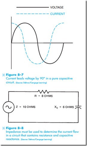
In a pure-capacitive circuit, the voltage and cur- rent are out of phase with each other. Figure 8–7 shows that the current in a pure-capacitive circuit leads the voltage by 90°. Because the voltage and current are 90° out of phase with each other, there is no true power or watts consumed in a pure- capacitive circuit. The capacitor stores the energy in an electro-static field, and then returns it to the circuit at the end of each half cycle.
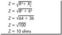
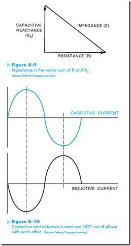
In the circuit shown in Figure 8–8, a resistor and capacitor are connected in series with each other. Since this circuit contains elements of both resistance and capacitive reactance, the current is limited by impedance. The impedance for a circuit
of this type can be found by using the formula Z = √R2 + X 2 . Notice this is the same basic formula as the one used to find the impedance of a circuit that contains both resistance and inductive reactance. The impedance of the circuit shown in Figure 8–8 can be found by the following:
Figure 8–9 shows a vector diagram of the circuit in Figure 8–8.
POWER FACTOR CORRECTION
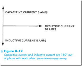
Because the current flow in a capacitive circuit leads the voltage by 90° and the current in an inductive circuit lags the voltage by 90°, the current of a capacitive circuit is in direct opposition to the cur- rent of an inductive circuit. Figure 8–10 illustrates the currents of capacitive and inductive circuits
as compared with each other. These two currents are 180° out of phase with each other. When the capacitive current is at its peak positive value, the inductive current is at its peak negative value. When the capacitive current is at its peak negative value, the inductive current is at its peak positive value. Because these two currents are in direct opposition, one can be used to cancel the other.
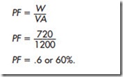
The circuit shown in Figure 8–11 shows a parallel circuit that contains a resistor, an inductor, and a capacitor. The applied voltage of the circuit is 120 volts at 60 Hz. Because this is a parallel circuit, the voltage applied to each component will be the same—120 volts. The resistor has a resistance of 12 ohms. This permits a current flow of 10 amps through the resistor (120/12 = 10). The inductor has an inductive reactance of 24 ohms. This permits a current flow through the inductor of 5 amps (120/24 = 5). The capacitor has a capaci- tive reactance of 24 ohms. This permits a current flow through the capacitor of 5 amps.
QUESTION
What is the total current flow in the circuit? In a parallel circuit, current is added. Therefore, it would appear that the current flow would be 20 amps (10 + 5 + 5 = 20). The currents of this circuit, how- ever, are out of phase with each other. Figure 8–12 shows a vector diagram of this circuit. Notice that the 5 amps of capacitive current is 180° out of phase with the 5 amps of inductive current. These two currents will cancel each other. The AC alternator sees only the resistance in this circuit. The current is, therefore, the same as the current flow through the resistor, or 10 amps.
POWER FACTOR CORRECTION OF A MOTOR
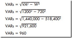
In the circuit shown in Figure 8–13, an AC induction motor is connected to a 120-volt line. A watt- meter is used to measure the amount of true power in the circuit. For this example it will be assumed that the wattmeter has a reading of 720 watts. An ammeter has also been inserted in the circuit. Assume the ammeter has a reading of 10 amps. The apparent power or volt-amp value for this circuit is 1,200 VA (120 volts x 10 amps = 1,200 VA). The power factor of this circuit can now be computed using the formula (PF = W/VA).
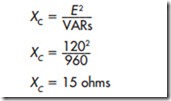
If the power factor of this motor is to be corrected, it must be determined how much of this circuit is comprised of true power and how much is composed of reactive power. Because the true power (watts) and the apparent power (volt-amps) is known, the reactive power (VARs) can be found using the following formula:
Because a motor is an inductive device, the reactive power in this circuit can be canceled by an equal amount of capacitive VARs. If a capacitor of the correct value is connected in parallel with the motor, the power factor will be corrected. To find the correct value of capacitance, determine the amount of capacitance needed to produce a VAR reading of 960. The amount of capacitive reactance can be found using the formula:
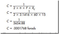
The amount of capacitance needed to produce 15 ohms of capacitive reactance at 60 Hz can be calculated using the following formula:
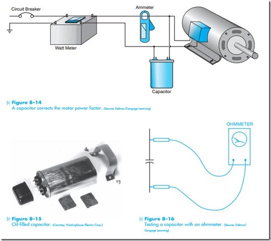
The answer for the value of C is in farads. To convert farads to micro-farads, multiply the answer by 1,000,000, or move the decimal point 6 places to the right .0001768 farads becomes 176.8 μf. If a capacitor of this value is connected in parallel with the motor as shown in Figure 8–14, the power factor will be corrected.
CAPACITOR TYPES
The most common types of capacitors used in the air conditioning field fall into two categories. One kind is known as an oil-filled type. Figure 8–15 shows a photograph of this type of capacitor. The oil-filled capacitor is made with two metal foil plates separated by paper. The paper is soaked in a special dielectric oil. These capacitors are true AC capacitors and are generally used as the run capacitors on many single-phase air conditioning compressors. They are also used as the starting capacitors on some units. The important ratings on these capacitors are the micro-farad rating and the voltage rating. The voltage rat- ing of a capacitor should never be exceeded. It is permissible to use a capacitor of higher voltage
rating, but never use a capacitor with less volt- age rating.
The second type of capacitor frequently used in air conditioning systems is the AC electrolytic capacitor. The AC electrolytic capacitor is used as the starting capacitor on many small single-phase motors. This type of capacitor is designed to be used for a short period of time only. If an AC electrolytic capacitor were to be used in a continuous circuit such as the running capacitor of a compressor, it would fail in a short period of time. The advantage of the AC electrolytic capacitor is that a large amount of capacitance can be housed in a small case size. This makes the AC electrolytic capacitor a good choice for starting circuits, because the capacitor is in the circuit for only a few seconds when the motor is started.
TESTING A CAPACITOR
Capacitors can be tested for a short with an ohm- meter. If an ohmmeter is connected across the terminals of a capacitor as shown in Figure 8–16, the meter should show a deflection up scale and then return to infinity ohms. The deflection up scale indicates current flow to the capacitor when it is being charged by the ohmmeter battery. If the leads of the ohmmeter are reversed, the meter should deflect twice as far up scale and then return to infinity ohms.
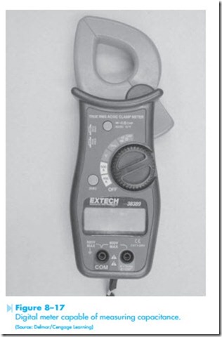
The ohmmeter test basically indicates if the capacitor is shorted or not. A short indicates the dielectric has been punctured. This test will not indicate a bro- ken plate, which would result in a lower capacitance value. Many digital meters contain a capacitance testing function, as shown in Figure 8–17. These meters actually measure the capacitance value, which can be compared to the rating marked on the capacitor.
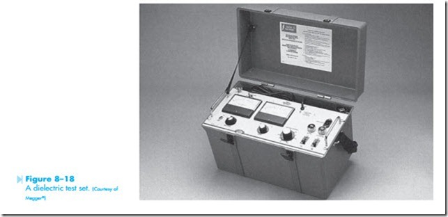
Neither of these tests, however, can measure the dielectric strength. A capacitor may test OK with an ohmmeter or digital meter but break down when connected to line voltage. Ohmmeters and common digital meters do not supply enough volt- age to test the dielectric at rated voltage. To test the dielectric strength, a dielectric test set should be used, as shown in Figure 8–18. The dielectric test set is sometimes referred to as a hipot because it provides a high potential or high voltage. The dielectric tester can provide rated voltage to the capacitor, and a microamperes meter measures any leakage current.
