AIR SEPARATORS
An air separator is a device used to trap, separate, and elimi nate air from the water in a hot-water space heating boiler. Air separators are not installed on boilers used only for heating the domestic water supply.
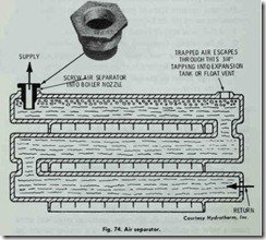
The air separator shown in Fig. 74 is screwed into the boiler supply nozzle. The separator traps the air in the top of the boiler section where the water is hottest and where it travels a long horizontal path at low velocity, permitting the air bubbles to sep arate. The trapped air escapes through a % inch tapping into an air cushion expansion tank or through an automatic float vent on systems using diaphragm expansion tanks.An air separator can only expel air which reaches ,the boiler. However, sometimes air pockets remain trapped in the piping or radiation, thereby impeding the water flow and reducing the heat ing performance of the boiler. Such air pockets can be eliminated by installing several different purge fittings in the heating system. A manual air vent is installed on the highest point of the system (automatic air vents are not generally required). See below.
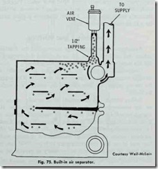
Some boilers are constructed with built-in air separators, which make the addition of an external unit unnecessary. Fig. 75 illus trates the working principles of one of these integral units. In this design, the air is diverted to an automatic air vent. A variation of this design provides for the diversion of air to an expansion tank. The manufacturer refers to this device as an air eliminator. Its function is similar to the air eliminator used on pipe lines, but it differs in design and construction.
PURGING AIR FROM THE SYSTEM
Built-in or externally installed air separators are designed to separate air from the water in an operating boiler, and vent it either into an expansion tank or to the atmosphere through an automatic air vent.
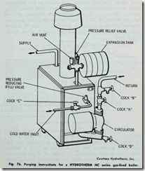
Air is also removed from a heating system by purging it from the piping connections to the boiler. This type of purging is stan dard when the system is being filled with water. Purging instruc tions are usually included in the owner’s manual or the manu facturer’s installation guide. Fig. 76 illustrates purging instructions for a Hydrotherm gas-fired boiler.
AIR SUPPLY AND VENTING
An adequate air supply must be provided for combustion to boilers that are fired by gas, oil, or coal, and the products of com bustion must be vented to the outside atmosphere.
Combustion air (i.e. the air supply) is normally supplied through venting ducts or openings in the walls. The requirements for the air supply will depend upon the location and enclosure of the boiler.
Boilers installed in unconfined areas usually obtain adequate air for combustion by means of normal infiltration. However, normal air infiltration will prove to be inadequate for this purpose, if the construction of the structure is unusually tight. Under these circumstances, provision must be made for the entry of additional air from outside the building. Unobstructed openings with a total free area of not less than one square inch per 5000 Btu/hr of the total input of the boiler will be necessary to provide an adequate air supply for combustion purposes.
Some boilers are installed in boiler rooms or enclosures which are supplied with combustion air from inside the structure. The air supply must enter and leave the boiler room through two open ings in an interior wall or door. One opening is located near the ceiling, the other opening near the floor. Each opening should have a free area of not less than one square inch per 1000 Btu/hr of the total input of the boiler.If a boiler is located in a boiler room or similar type enclosure which receives its air supply from outside the building, the two air openings are located on an exterior wall. Each opening must have a free area of not less than one square inch per 4000 Btu/hr of the total input of the boiler.
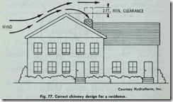
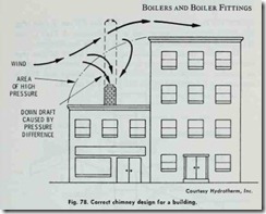
The products of combustion must be vented to the outside atmosphere. In order to accomplish this, the boiler must be con nected to a suitable venting system which should include a flue pipe and a chimney or stack of adequate size and capacity.The chimney height is usually governed by the height of the structure. As a general rule-of-thumb, the chimney should ex tend beyond the high pressure area caused by the passage of 10 feet of the flashing. If the chimney is too short, it will not ex tend beyond the high pressure area caused by the passage of winds over the structure. As a result, a down draft caused by the pressure difference in the high pressure area will suck air down into the chimney, which will block the escape of flue gases and interfere with the combustion process. Figs. 77 and 78 illustrate these principles. The correct chimney height is shown by the dotted lines.
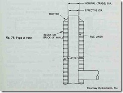
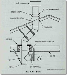
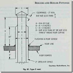
Fig. 79 shows a type of chimney construction that is referred to as a Type A vent. This type of chimney can be either masonry or factory built construction, but it must be designed and con structed in accordance with the standards set forth in national codes. Type A vents are suitable for venting of all gas appliances. These are the only vents suitable for venting oil burning equip ment. Gas-fired boilers which produce temperatures at the draft diverter not in excess of 550°F may also use a Type B vent (Fig. 80), which employs a double wall metal vent pipe. A Type C vent (Fig. 81) is used to vent gas appliances in attic instaiiations.
The boiler should be located so that the length of flue pipeconnecting the boiler (or draft diverter) to the chimney is as short as possible. Additional information about chimneys and flues is contained in Chapter 11 (GAS-FIRED FURNACES).
