The Comfort Chart
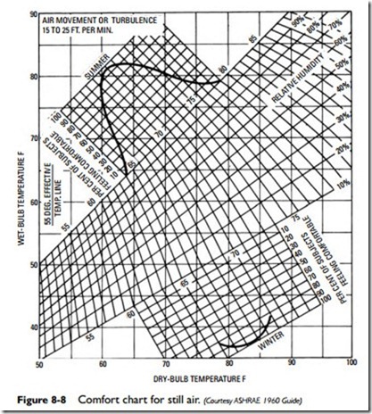
The comfort chart (see Figure 8-8) is an empirically determined effective temperature index that has been published by the ASHRAE since 1950.
The purpose of the comfort chart is to indicate the percentage of people feeling comfortable at various effective temperatures in the winter and summer. This serves only as an approximate standard of comfort, because individual reactions to warmth and cold are much too variable, but it is the most precise and scientific form of measurement available.
From the chart, one can obtain an approximate idea of the various effective temperatures at which a majority of people will feel comfortable (that is, the summer and winter comfort zones).
Most air-conditioning systems are designed with a recommended indoor design relative humidity of about 50 percent or slightly lower. Budget jobs will range as high as 60 percent relative humid- ity. The indoor dry-bulb temperature will range from 75°F or slightly below to about 80°F, depending on the degree of occupancy and whether it is a budget job or not. In any event, the indoor design conditions should fall within the comfort zone.
More information about the use of the comfort chart is included in Appendix E (“Psychrometric Charts”).
Cooling Load Estimate Form
Air-conditioning equipment manufacturers often provide their local representatives with forms for making cooling load estimates. Along with these forms they also provide tables, slide charts, tabulation sheets, and other aids for computing the cooling load.
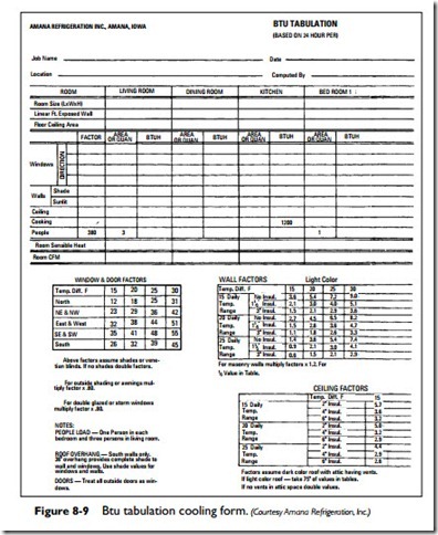
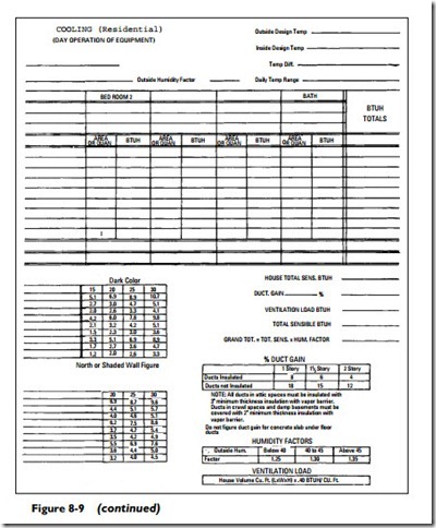
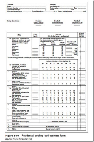
Typical tabulation sheets and cooling load estimate forms are shown in Figures 8-9 and 8-10. These forms contain lists of factors that represent approximate values for a variety of different items (for example, walls, ceilings, people). For example, the form illustrated in Figure 8-9 requires that you select the appropriate design dry-bulb temperature and its column of factors. After calculating the area (in square feet) of the structural section, you must multiply this figure by its factor to determine the Btu per hour of heat gain and enter the result in the column on the extreme right.
Because a manufacturer’s cooling estimate form will probably not be available, it may be necessary to create your own. If this should be the case, then provisions should be made on the cooling estimate form for distinguishing between sensible and latent heat sources.
Your cooling load estimate form should contain the following basic categories of heat gain:
A. Sensible heat gain
1. Heat leakage
2. Solar radiation
3. Internal heat sources
4. Infiltration
5. Ventilation
6. Electric lights
7. Electric motors
8. People
9. Appliances
B. Latent heat gain
1. Infiltration
2. Ventilation
3. People
C. Ventilation heat gain (from outside sources)
1. Sensible heat
2. Latent heat
The sum of these categories will represent the total heat gain expressed in Btu per hour. A balance must be established between
this hourly heat gain within the conditioned space and the hourly capacity of the air-conditioning unit to remove this heat gain in order to maintain the inside design temperature.
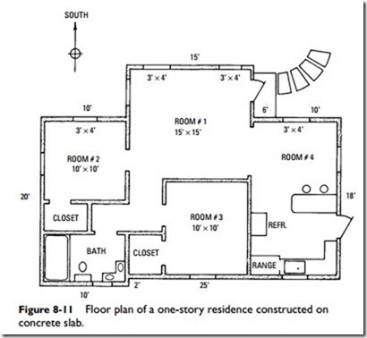
Figure 8-11 is a floor plan (not drawn to scale) of a house that will serve as a basis for most of the cooling calculations used in this chapter.
The house is located 30° north, and complete exposure to the sun occurs at 1:00 P.M. The structure contains 740 square feet of floor space divided into four rooms and a bath. There are ten 3′ × 4′ windows, with four of them facing south. The indoor design tem- perature is 80°F.
Related posts:
Incoming search terms:
- comfort chart
- comfort chart air conditioning
- human comfort chart
- comfort chart and effective temperature
- what is comfort chart
- what is human comfort chart
- effective temperature in air conditioning
- application of comfort chart
- comfort chart in hvac
- what is effective temperature in air conditioning
- comfort chart comfort air conditioning
- comfort chart in air conditioning
- Ac comfort chart
- comfort cha
- what is human comfort and draw the chart
- human comfort air conditioning
- air comfort zone pchycrometric
- use of comfort chart
- explain comfort chart
- charts used in air conditioning system
- effective temperature in refrigeration
- effective temperature inrefrigeration and air conditioning
- How to measure effective temperature and comfort chart
- concept of effective temperature in air conditioning
- confort chart
- cooling load estimate form
- define effective temperature in air conditioning units
- define effective temperature in air conditions
- effective temperature and comfort chart
- EFFECTIVE TEMPERATURE IS REPRESENTED BY_______IN COMFORT CHART *
- effective temperature comfort chart
- factors in load estimation for comfort condition
- Effective temtemperature air conditioning
- effective temperature in refrigeration and airconditioning
- comfort chart and comfort zone in refrigeration
- air conditioning comfort chart
- brief note on human comfort chart
- comfort air conditioning temp for humans
- comfort airconditioning chart
- comfort cbart
- comfort ch
- comfort chart air conditioning in car pdf
- Comfort chart and uses
- comfort chart diagram
- air conditioning for human comfort and comfort chart
- Comfort chart in Psys
- comfort chart in r&ac
- comfort chart in rac
- comfort chart of air conditioning system
- comfort chart pdf
