The Pelton turbine
This is the only hydraulic turbine of the impulse type now in common use. It is an efficient machine and it is particularly suited to high head applications. The rotor consists of a circular disk with a number of blades (usually called buckets) spaced around the periphery. One or more nozzles are mounted in such a way that each nozzle directs its jet along a tangent to the circle through the centers of the buckets. A “splitter” or ridge splits the oncoming jet into two equal streams so that, after flowing round the inner surface of the bucket, the two streams depart from the bucket in a direction nearly opposite to that of the incoming jet.
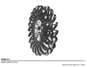
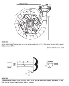
Figure 9.3 shows the runner of a Pelton turbine and Figure 9.4 shows a six-jet vertical axis Pelton turbine. Considering one jet impinging on a bucket, the appropriate velocity diagram is shown in Figure 9.5. The jet velocity at entry is c1 and the blade speed is U so that the relative velocity at entry is w1 5 c1 2 U. At exit from the bucket, one half of the jet stream flows as shown in the velocity diagram, leaving with a relative velocity w2 and at an angle β2 to the original direction of flow. From
the velocity diagram, the much smaller absolute exit velocity c2 can be determined.1
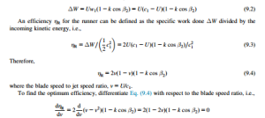
From Euler’s turbine equation, Eq. (1.18c), the specific work done by the water is
The effect of friction on the fluid flowing inside the bucket will cause the relative velocity at outlet to be less than the value at inlet. Writing w2 5 kw1, where 0:8 # k # 0:9.
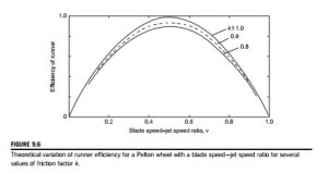
Therefore, the maximum efficiency of the runner occurs when ν 5 0.5, i.e., U 5 c1/2. Hence,
Figure 9.6 shows the theoretical variation of the runner efficiency with blade speed ratio for assumed values of k 5 0.8, 0.9, and 1.0 with β2 5 165o. In practice, the value of k is usually found to be between 0.8 and 0.9.
A simple hydroelectric scheme
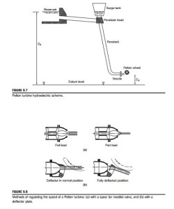
The layout of a Pelton turbine hydroelectric scheme is shown in Figure 9.7. The water is delivered from a constant level reservoir at an elevation zR (above sea level) and flows via a pressure tunnel to the penstock head, down the penstock to the turbine nozzles emerging onto the buckets as a high-speed jet. To reduce the deleterious effects of large pressure surges, a surge tank is connected to the flow close to the penstock head, which acts so as to damp out transients. The elevation of the nozzles is zN and the gross head, HG 5 zR 2 zN.
Controlling the speed of the Pelton turbine
The Pelton turbine is usually directly coupled to an electrical generator that must run at synchronous speed. With large size hydroelectric schemes supplying electricity to a national grid, it is essential for both the voltage and the frequency to closely match the grid values. To ensure that the turbine runs at constant speed despite any load changes that may occur, the rate of flow Q is changed. A spear (or needle) valve, Figure 9.8(a), whose position is controlled by means of a servo- mechanism, is moved axially within the nozzle to alter the diameter of the jet. This works well for
very gradual changes in load. However, when a sudden loss in load occurs, a more rapid response is needed. This is accomplished by temporarily deflecting the jet with a deflector plate so that some of the water does not reach the buckets, Figure 9.8(b). This acts to prevent over-speeding and allows time for the slower acting spear valve to move to a new position.
It is vital to ensure that the spear valve does move slowly as a sudden reduction in the rate of flow could result in serious damage to the system from pressure surges (called water hammer). If the spear valve did close quickly, all the kinetic energy of the water in the penstock would be absorbed by the elasticity of the supply pipeline (penstock) and the water, creating very large stresses, which would reach their greatest intensity at the turbine inlet where the pipeline is already heavily stressed. The surge tank, shown in Figure 9.7, has the function of absorbing and dissipating some of the pressure and energy fluctuations created by too rapid a closure of the needle valve.
Sizing the penstock diameter
It is shown in elementary textbooks on fluid mechanics (e.g., Franzini & Finnemore, 1997; White, 2011) that the loss in head with incompressible, steady, turbulent flow in pipes of circular crosssection is given by the Darcy-Weisbach equation (often referred to simply as Darcy’s equation):
where f is the friction factor, l is the length of the pipe, d is the pipe diameter, and V is the mass average velocity of the flow in the pipe. It is assumed, of course, that the pipe is running full. The value of the friction factor has been determined for various conditions of flow and pipe surface roughness, e, and the results are usually presented in what is called a Moody diagram. The penstock (the pipeline bringing the water to the turbine) is long and of large diameter and this can add significantly to the total cost of a hydroelectric power scheme. Using Darcy’s equation, Eq. (9.6), it is easy to calculate a suitable pipe diameter for such a scheme if the friction factor is known and an estimate can be made of the allowable head loss. Logically, this head loss would be determined economically on the cost of materials, etc., needed for a large diameter pipe and compared with the value of the useful energy lost from having too small a pipe. A commonly used compromise for the loss in head in the supply pipes is to allow Hf # 0.1HG.
A summary of various other factors on which the “economic diameter” of a pipe can be determined is given by Raabe (1985).
From Eq. (9.6), substituting for the velocity, V 5 4Q/(πd2), we get
Energy losses in the Pelton turbine
Having accounted for the energy loss due to friction in the penstock, the energy losses in the rest of the hydroelectric scheme must now be considered. The effective head, HE (or delivered head), at entry to the turbine is the gross head minus the friction head loss, Hf, i.e.,
and the spouting (or ideal) velocity, co, is
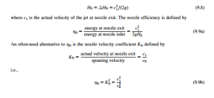
The pipeline friction loss Hf is regarded as an external loss and is not usually included in the losses attributed to the turbine itself. The performance and efficiency of the turbine are, in effect, measured against the total head, HE, as shown in the following.
The main energy losses of the turbine occur in
i. the nozzles due to fluid friction;
ii. converting the kinetic energy of the jet into mechanical energy of the runner;
iii. external effects (bearing friction and windage).
Each of these energy losses are now considered in turn.
For item (i), let the loss in head in the nozzles be ΔHN. Thus, the available head is
Optimum jet diameter
For any given penstock, there will be a unique jet diameter that will provide a maximum power to the jet. The power available in the jet is given by
where c1 is the velocity of the jet.
To give further weight to the above statement, consider allowing the flow rate Q to slowly increase, initially allowing the power to increase. As a result of this, the frictional losses must increase and the jet velocity will be reduced. It will be apparent from the above equation that there will be some flow rate at which the power must be at a maximum. This is illustrated in Example 9.1.
EXAMPLE 9.1
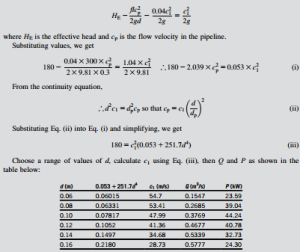
Water is supplied to the nozzle of a Pelton turbine through a single penstock 0.3 m internal diameter and 300 m long from a reservoir whose surface level is 180 m above the centerline of the nozzle. The friction factor for the penstock is f 5 0.04. The head loss of the flow in the nozzle is 0:04c2=ð2gÞ. Determine the jet diameter that will give the maximum power in the jet.
The energy equation for the pipe flow can be written as
The maximum power for the jet is 44.24 kW at d 5 0.10 m.
Of course it is possible to obtain a solution for the jet diameter and maximum power by set- ting up an expression for the power and differentiating with respect to the diameter. The advantage of the tabular method used here is that of being able to observe the variations of the various factors with the change in diameter of the jet.
As an exercise, it would be useful to determine the nozzle efficiency, ηN, as given in Eq. (9.9a). We must first calculate HE 5 Hg 2 Hf, where
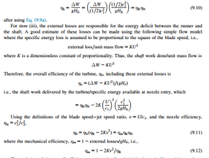
For item (ii), the loss in energy is already described in Eq. (9.2) and the runner efficiency, ηR, by Eqs (9.3) and (9.4). The turbine hydraulic efficiency, ηh, is defined as the specific work done by the rotor, ΔW, divided by the specific energy available at entry to the nozzle, gHE, i.e.,
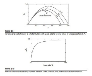
The variation of the overall efficiency as given by Eq. (9.11) is shown in Figure 9.9 as a function of v for several values of the windage coefficient K. It will be noted that peak efficiency reduces as the value of K is increased and that it occurs at lower values of v than the optimum for the runner. This evaluation of the theoretical performance of a Pelton turbine gives a possible
reason for the often puzzling result found when experiments are evaluated and that always yield a peak efficiency for values of v , 0.5.
By differentiating Eq. (9.11), it can be shown that the optimum value of v occurs when
Exercise
Let k 5 0.9, β2 5 165o, and K 5 0.1. Hence, A 5 1.869 and ν 5 0.475.
Typical performance of a Pelton turbine under conditions of constant head and speed is shown in Figure 9.10 in the form of the variation of overall efficiency against load ratio. As a result of a change in the load, the output of the turbine must then be regulated by a change in the setting of the needle valve to keep the turbine speed constant. The observed almost constant value of the effi- ciency over most of the load range is the result of the hydraulic losses reducing in proportion to the power output. However, as the load ratio is reduced to even lower values, the windage and bearing friction losses, which have not diminished, assume a relatively greater importance and the overall efficiency rapidly diminishes toward zero.
EXAMPLE 9.2
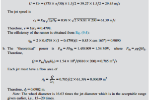
A Pelton turbine is driven by two jets, generating 1.4 MW at 375 rpm. The effective head at the nozzles is 200 m of water and the nozzle velocity coefficient, KN 5 0.98. The axes of the jets are tangent to a circle 1.5 m in diameter. The relative velocity of the flow across the buckets is decreased by 15% and the water is deflected through an angle of 165o.
Neglecting bearing and windage losses, determine
a. the runner efficiency;
b. the diameter of each jet;
c. the power specific speed.
Solution
a. The blade speed is
c. Substituting into Eq. (9.1), the power specific speed is
Related posts:
Incoming search terms:
- Losses in Pelton turbine
- whatis windage loss on pelton turbine
- maximum efficiency of pelton turbine
- machine equipment hvac hydraulic turbine pelton
- power loss inthe nozzle pelton turbine
- power losses in pelton turbine
- formula weight runner vertical pelton turbine
- power lost in runner of pelton wheel
- requivolumioito
- what is windage loss in pelton turbine
- pilton turbine example
- Pilton turbine C17
- pelton turbine losses
- nozzle velocity coefficient head loss
- machibe equipment hvac pelton
- kaplan specific work equation
- In Pelton turbine product of mechanical efficiency and hydraulic efficiency is known as _____________ * 2 points a) Mechanical efficiency b) Volumetric efficiency c) Hydraulic efficiency d) Overall efficiency
- head loss in pelton turbine
- formulas using coefficient of velocity in pelton
- windage loss in pelton turbine


