PQ Concept and Fundamentals
The industry standards such as IEEE, ANSI, and NEMA specify steady state voltage tolerances for the electric utility at the point of service to be within ±5% for nonlighting loads. These standards also specify the steady state voltage tolerances at the point of use. Equipment utilizing electricity must be designed to give satisfactory performance throughout the range of +4% to −10%, and acceptable performance in the broader range of +6% to −13%. However, this specification of steady state voltage limits is insufficient for today’s microelectronic technology. What constitutes acceptable performance and acceptable PQ for computers is more difficult to define. A comprehensive definition of PQ is needed. It should be based on consideration of the following:
• All types of power disturbances that occur
• Quality of power necessary for successful operation of diverse electrical and electronic equipment
• Practical limits to the capability of delivering power of high quality to diverse customers
• Economics of the electric power distribution from both the utility and customer perspective
One definition proposed by the IEEE-1100 describes PQ as a concept of powering and grounding sensitive electronic equipment in a manner that is suitable to the operation of that equipment.
12.2.1 Types and Consequences of Electrical Disturbances
Several different types of electrical disturbances can occur in a power distribution system as described briefly below.
Voltage disturbances: The interaction between sensitive electronic equipment, their power sources, and their electrical environment can result in distortions to the alternating current (AC) line voltage. Several common load derived sources of voltage waveform disturbances and their relative characteristics are presented below.
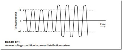
Overvoltage: An overvoltage is any change above the prescribed input volt- age range for a given piece of equipment (Figure 12.1). Overvoltages can be caused by many factors in the utility and customer’s supply voltage system, such as incorrect transformer tap settings, improper application of power factor (PF) correction capacitors, and the like. They can cause overheating and reduced life of electrical equipment.
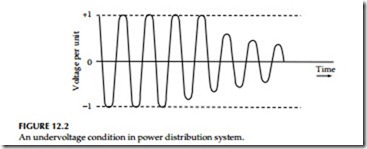
Undervoltage: An undervoltage is any change below the prescribed input voltage range for a given piece of equipment (Figure 12.2). Undervoltages can be caused by many factors in the power supply and/or in the site distri- bution power system. Undervoltage can occur due to overloaded distribution systems or customer wiring, incorrect transformer tap setting, faulty connections or wiring, loose or corroded connections, or unbalanced phase
loading conditions. They cause a range of problems from errors in sensitive equipment to hardware damage, low efficiency, and reduced life of electrical equipment (e.g., some motors and heaters).
Voltage dip (sag): A momentary voltage dip is referred to as sag. Sag is a voltage dip of momentary (0.5–180 cycles) reduction in voltage (0.1–0.9 PU) at the power frequency beyond a particular piece of equipment’s utilization voltage tolerance a shown in Figure 12.3. Voltage dip can be caused by faults on the power system (remote or in adjacent feeders), indirect lightning effects, overloaded or undersized wiring and incorrect fuse rating, utility switch- ing/equipment failure, and start-up of large loads (motors, air condition- ers, electric furnaces, etc.). They cause power-related computer systems failures, motor stalling, and overheating of motors and electrically driven equipment. (Voltage dip and sag terms are used interchangeably in this chap- ter to define the same occurrence.)
Transients: A transient voltage surge (TVS) can occur on power lines and conductors, including telecommunications and data line links. It is a significant deviation from normal AC voltage sine wave, typically lasting from a fraction of 1 μs up to 5 ms. A TVS can be categorized as a deviation generated from a natural occurrence (lightning) or through the switching of power equipment, either on-site or elsewhere. Irrespective of the cause of the TVS, the electric charge enters the power lines and conductors at some point and the influx of charge causes voltage there to rise in a manner determined by the system capacitance. The electric charge then spreads through the system in the form of traveling waves which redistribute its energy.
Various forms of TVS are discussed below.
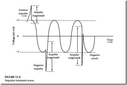
Impulse transient: An impulse transient has a fast rise time, fairly rapid decay, and high energy content. Duration can be from a few microseconds up to several hundred microseconds. A typical impulse transient is shown in Figure 12.4. Its impulse magnitude is measured from the point it occurs on the sine wave and not from zero voltage. It is called a spike, if it adds to the sine wave, or a notch, if it subtracts from the sine wave.
The voltage impulse is a high-frequency voltage phenomenon of positive (spike) or negative amplitude (notch). An impulse occurring between current- carrying conductors is known as normal mode event and an impulse common to all current-carrying conductors and involving the ground conductor is referred to as common mode (CM) event. Many impulses have components of both types. Another type of repetitive voltage disturbance is a series of events with discrete components which occur repetitively throughout a single cycle or regularly multiple cycles. These repetitive voltage disturbances are usually caused by phase-angle-controlled loads, such as silicon-controlled rectifiers (SCRs). The impulse factors which affect the loads are impulse amplitude, duration, fre- quency, grounding, etc. Over time the cumulative effect of repetitive voltage disturbances can exceed the energy handling capability of the loads, thus resulting in a catastrophic failure. The symptoms of this type of disturbance are indicated by equipment component failures, hard disk crashes, parity errors, power supply failures, lockup, circuit board failures, surge suppressor failures, etc.
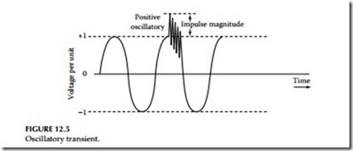
Oscillatory transient: An oscillatory transient has a fast rise time, oscillations that decay exponentially, and a lower energy content than an impulse transient. A typical oscillatory transient can last up to one cycle (16.7 ms) or even longer and can have frequencies from a few hundred hertz to many megahertz. A typical oscillatory transient is shown in Figure 12.5.
Switching transient: Switching of power equipment can cause a transient voltage to be generated due to the stored energy contained in the circuit inductances (L) and capacitances (C). The size and duration of the transient depends on the value of inductance and capacitance and the waveform applied. Examples of switching surges are fault clearing, capacitor switch- ing, and switching of inductive loads on and off. Damage from transient overvoltages can be immediate or latent. The latent damage occurs when equipment or components are severely stressed by repeated transient over- voltages or by a single transient overvoltage condition, but not to the point of immediate failure. Each exposure reduces the ability of the equipment or component’s ability to withstand additional stress. At some later time, the equipment or component fails unexpectedly without apparent cause due to its weakened nature from previous transients. This latent effect may not become apparent for some time.
Interruptions: Power interruptions are a complete loss of power lasting for cycles, seconds, minutes, hours, or days (Figure 12.6). A variety of factors can cause power interruptions, such as tripping of the main circuit breaker due to a fault, malfunction or failure of equipment, or operation of protective devices in response to faults that occur due to acts of nature or accidents, or other anomalies in the power supply. These interruptions may cause loss of computer memory, equipment shutdown/failure, hardware damage, and productivity loss.
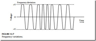
Frequency variations: A frequency variation is a deviation from a prescribed input frequency range such as 60 Hz (Figure 12.7). This deviation can be either higher or lower than normal. Sudden changes in load, switching of power
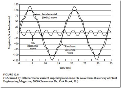
Harmonics: Harmonics are voltages or currents at frequencies that are integer multiples of 60 Hz frequency (120, 180, 240, 300 Hz, etc.). They are designated by their harmonic number or multiple of the fundamental frequency. For example, a harmonic with a frequency of 180 Hz—(three times the 60 Hz fundamental frequency) is called the third harmonic. As shown in Figure 12.8, harmonics superimpose themselves on the fundamental waveform, distort it, and change its waveform. In industrial power systems, for example, 15%, 20%, or 25% total harmonic current distortion (THD) may be experienced. THD can be determined by calculating the square root of the sum of the squares of all harmonics, divided by the nominal 60 Hz value. This yields
a root-mean-square (rms) value of distortion as a percentage of the 60 Hz waveform. Note, odd-order harmonic currents are additive in the common neutral of a three-phase system, whereas the even-order harmonics cancel out to zero. The odd-order harmonic currents such as the third and all odd multiples of the third harmonic (9th, 15th, etc.) are equal and in phase for a three-phase, four-wire system. Therefore, they add in the neutral. Other odd harmonics (5th, 7th, 11th, etc.) are also additive, although not fully since they are equal but not exactly in phase. Mathematically, the total is a vector sum of the three-phase harmonic currents. The phase angles between the three- phase harmonic currents results in partial addition and partial cancellation. Therefore, the total neutral current for these harmonics is more than any one harmonic phase current, but less than three times any harmonic phase current. Whereas for the second harmonic and all even harmonics (fourth, sixth, eighth, etc.), currents are not in phase and the sum of the positive and negative neu- tral currents equals to zero for a three-phase, four-wire system. Harmonics are caused by nonlinear loads, that is loads in which the current waveform does not conform to the waveform of applied voltage. All equipment operating on the principle of ferromagnetic induction (lighting ballasts, lifting magnets, solenoids, motors, etc.) produces some degree of harmonics. A prime example of a device that produces harmonics is a power converter such as a rectifier that draws current in only a portion of each cycle. Other devices, such as those which change impedance with applied voltage, also produce harmonics. These include saturated transformers and gaseous discharge lighting, such as fluorescent, mercury arc, and high pressure sodium lights.
Harmonics can cause overloading of conductors and transformers and overheating of utilization equipment, such as motors. Odd-numbered triplen harmonics (3rd, 9th, 15th, etc.) can especially cause overheating of neutral conductors on three-phase, four-wire systems. While the fundamental fre- quency line currents and other even harmonic currents cancel each other in the neutral, the triplen harmonic and other odd harmonic currents are addi- tive in the neutral. Harmonics also can cause nuisance tripping of molded- case circuit breakers and power switchgear equipped with solid-state trip-sensing units designed to sense peak (as opposed to rms) current. As increased amounts of sensitive electronic equipment are being added to today’s workplaces, concern for harmonics has escalated as well. Electronic equipment miss operation can result from harmonics because much of elec- tronic circuitry—notably that in which action is instigated by an electronic pulsing clock—is triggered by zero crossing on the waveform.
Harmonic currents may contribute to capacitor failure and blown fuses on PF improvement capacitors under resonance conditions on the power system. Resonance occurs when the power system inductance and capacitance come in tune (i.e., equal) with each other at a particular frequency; capacitive and inductive reactance are both functions of frequency. Every circuit containing inductive and capacitive devices has one or more resonant frequencies. Resonance can cause very high voltages to appear across elements of the power system. At series resonance, minimum circuit impedance occurs at the resonant frequency and is equal to the resistance of the circuit since the
inductive and capacitive impedances are equal. Series resonance provides a low impedance path for the harmonic currents present in the system.
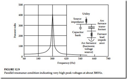
Figure 12.9 illustrates a typical resonant condition on an arc furnace cir- cuit containing PF improvement capacitors. The plot of voltage response versus frequency models the arc furnace as a harmonic current source of varying frequency. A resonance peak occurs at very close to 300 Hz, or the fifth harmonic. This harmonic source develops excessive voltage at the capacitor terminals, resulting in extremely high current flow through the capacitor.
Voltage imbalance: A voltage imbalance is a long term, steady state problem. It is expressed as a percent, i.e., the maximum deviation of voltage from the average of three-phase voltages, multiplied by 100, divided by the average of the voltages. Voltage imbalances are caused by unbalanced phase loading conditions, defective transformers, and ground faults in ungrounded or resistive grounded systems. These imbalances usually are caused by large single- phase loads. They cause premature failures of motors and transformers due to overheating. Voltage imbalances only affect three-phase applications.
Electrical noise: Electrical noise is a low-voltage, low-current, high-frequency signal that rides a 60 Hz sine wave, distorting it. Noise may be caused by any of the following: RFI, EMI, harmonics from nonlinear loads, and the like. Even though microprocessor-based equipment is grounded in accordance with National Electric Code (NEC) requirements, some continue to have failures, execution and reading errors, and unpredictable and intermittent operations because of electrical noise. Some manufacturers of microprocessor-based equipment recommend electrical separation to minimize the effects of electri- cal noise, i.e., to locate the microprocessor-based equipment and/or data lines not too close to large power apparatus such as transformers, motors, etc.
Two types of electrical noise can occur in a power distribution system. They are normal mode (line-to-neutral, L–N or line-to-line) noise and CM (neutral-to-ground, N–G) noise.
Normal mode noise is measured between the phase (hot) and neutral lines or phase-to-phase. CM noise is a potential difference that occurs between any or all current-carrying conductors and the grounding conduc- tor or earth. In the three-phase, grounded-wye power supplies typical of large computer systems, these disturbances also can be potential differences between neutral and ground. Some computer-based loads are sensitive to excessive levels of voltage potential between the neutral and grounding conductors. A ground is used to reference the electronic logic in equipment and should be stable. Equipment manufacturers sometimes specify acceptable limits for neutral to ground voltage, for example, one volt peak to peak. CM disturbances can be generated by a ground potential difference between elements of the computer or remote peripherals connected to the computer. This type of disturbance is influenced by several factors, including the system configuration and the impedance of the grounding system. Both of these factors generally are beyond the direct control of the user, except in the construction of a new facility. However, CM noise can be suppressed by the use of an isolation transformer. Equalizing ground potentials is often difficult due to the broad frequency band involved in wiring resonances. However, proper computer system grounding, including a signal reference grid (SRG), has been found to be effective against most CM disturbances. CM noise on the primary of the transformer that appears as normal mode noise on the secondary is commonly referred to as transverse mode or sometimes as intercoupling or differential mode (DM) noise. CM transient voltages that appear on the transformer primary winding will be coupled through the transformer interwinding capacitance, appearing across the secondary winding as normal mode voltages. Electrical noise typically occurs in the RF MHz range. It also may occur at frequencies below MHz range. The 60 Hz (power) grounding system often is not effective for conducting RF signals to the common reference point grounding electrode. In some cases, computers and peripherals are themselves responsible for generating noise disturbances. A properly designed power grounding system has sufficiently low impedance at 60 Hz to maintain enclosures, raceways, and all grounded metals at the same voltage potential (ground reference). But the 60 Hz ground system is unable to provide this equalization at higher frequencies because of the increased impedance caused by inductive reactance and the skin effect. (Skin effect is known as the tendency of current to flow more at the surface of the conductor than its center, thereby increasing the AC resis- tance of the conductor). The inductive reactance at a frequency of 30 MHz is 500,000 times as great as that of the same conductor when the applied voltage is at 60 Hz. At microprocessor switching speeds (over 1 to 30 MHz), current penetration in the copper conductor is less than at 60 Hz, with the result that the effective impedance between one point and another is pronounced. Also, as frequency rises, the wavelength proportionally decreases. Circulating (noise) currents see an apparent open circuit at intervals of one-quarter wavelength, so that the current path is interrupted or becomes unreliable. Some frequencies pass and some do not, causing dis- tortion. Consequently, the long grounding conductors used in the ground- ing systems designed to meet NEC requirements become ineffective for grounding of high-frequency systems. Short returns are always recom- mended for fast-rise circuits to provide effective signal returns at system signal frequencies.
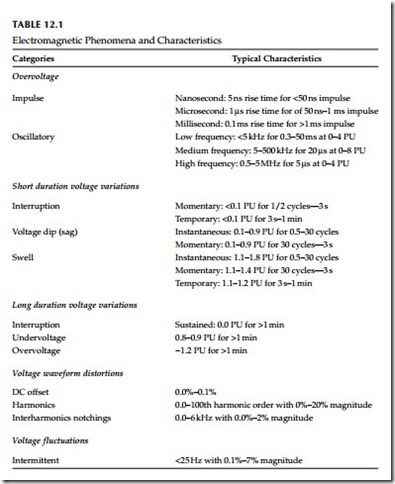
Table 12.1 is a summary of the electromagnetic phenomena categories and their characteristics of the power system.
