System Model
In order to analyze the electric power using the network percolation approach, the first thing to do is to construct a graph from the system model [12]. From the perspective of network theory, a graph is an abstract representation of a set of objects, called nodes or vertices, where some pairs of the objects are connected via links or edges.
To portray the assemblage of various components of the power system, engi- neers use single-line or one-line diagrams, which provide significant information about the system in a concise form [13]. Power is supplied from the generator nodes to the load nodes via transmission and/or distribution lines. The principle of constructing a graph from the single-line diagram of the power grid is described as follows [14]:
• all impedances between a bus and neutral are neglected,
• all transmission and/or distribution lines are modeled except for the local lines in plants and substations,
• all transmission lines and transformers are modeled as weighted lines, the weight is equal to the optimum power flowing in the network, and
• parallel lines between buses are modeled as equivalent single lines.
A power system network is represented by a graph G ¼ ðV; E; WÞ comprising of a set V, whose elements are called vertices or nodes, a set E of ordered pairs of vertices, called edges or lines. An element e ¼ ðx; yÞ of the edge set E, is considered to be directed from x to y; where y is called the head, and x is called the tail of the edge. A set W, whose elements are weights of the edge set elements. There exists a one-to-one correspondence between set E and set W. In this model, we consider the transmission line impedances in pu as weights of the edges between nodes.
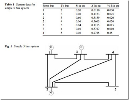
A simple example of 5 bus system [15] is used in this chapter to illustrate various concepts of complex network in the power system. Figure 1 depicts the system with 5 bus bars, and 7 links connecting them. We can model the system as a graph which contains 5 nodes/vertices, which correspond to the slack, voltage- controlled, and load bus bars of the original system. The transmission lines can be represented by the 7 links/edges which connects various nodes. The system data are given in Table 1.

