Enabling the HVDC System to Deliver Frequency Response
There are several challenges that de future power systems will face in coming future. One of them is meets rising energy requirements in a manner that is sustainable, secure, and competitive. There is no single answer for this situation; however, there are several aspects to consider regarding primary resource [47, 48]:
(i) greater energy efficiency and conservation, (ii) increased use of resources that are secure, indigenous, sustainable, clean, and competitive.
A potentially realistic solution for this situation is the use of a primary energy source, which is a clean, and fuel cost-free, wind power. This resource is enormous in the Europe’s offshore and the amount available is able to meet Europe’s demand seven times over. There are 150 GW on offshore wind projects are already at various stages of planning and development. The North Sea has a vast potential for renewable energy generation: offshore wind power, tidal and wave energy.
High Voltage Direct Current (HVDC) systems are more flexible than their AC counterparts and it offers distinct advantages for the integrating offshore wind farms to inland grid system. The Voltage Source Converter (VSC) HVDC trans- mission system enable fast and flexible control active and reactive power, and can alleviate the propagation of voltage and frequency deviations due to wind variations in wind strength. It seems advances on technologies open the door for VSC HVDC systems at higher voltage and higher power range, which is making multi- terminal HVDC (MTDC) system a technical possibility [47].
Wind power evolution in Northern Europe is foreseen to continue in the future with development of large-scale wind power on far offshore. Integration scheme of these wind farms to the onshore grids would grow from point-to-point connection to a transnational multiterminal network where the transmission capacity serves both to evacuate the wind power and to facilitate power trading between countries.
Supergrid will be the transmission backbone of Europe’s decarbonized power sector. It will facilitate the trading of electricity across and it will strengthen security of supply [49].
Although the Supergrid has gotten much attention, it cannot be built yet. Many Supergrid topologies have been proposed or studied by different organizations [50–52]. Regulatory and policies aspects have been defined: A single planner (European Network of Transmission System Operators for Electricity, Entso-e), a single operator (ISO), a single grid code (Entso-e), and a single European regulator (ACER). However, North Sea Supergrid can probably not be built as a planned and optimally structure [48].
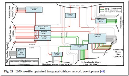
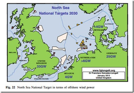
The main reason, independently planned projects would be coupled together, leading to a rather grown network, comprising several DC and AC voltage levels and maybe different frequencies. The 2030 Possible optimized integrated offshore network development based on results of Entso-e is depicted on Fig. 21. It is based on the national target in terms of offshore wind power for North Sea national, scenario 2030, it was created by European Wind Energy Association (EWEA), and depicted in Fig. 22. Large offshore DC links in excess of several gigawatt may have several capabilities to enhance the grid stability [53].
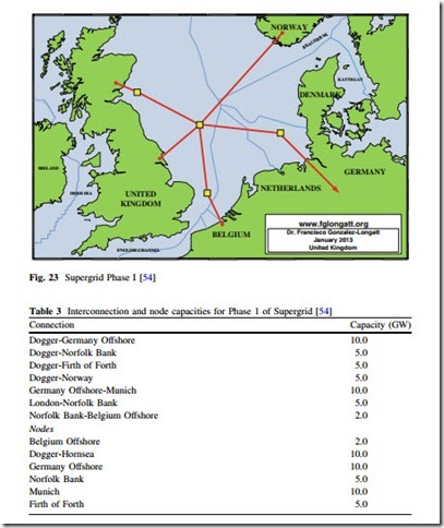
The Supergrid will be built out in phases, initially connecting the current crop of offshore wind generators to existing networks. As a first step, (Phase 1) nodes will be built in the North Sea using 2015 technology to cluster offshore wind
generation for bulk delivery. Figure 23 shows a proposal scheme for Phase 1 of Supergrid.
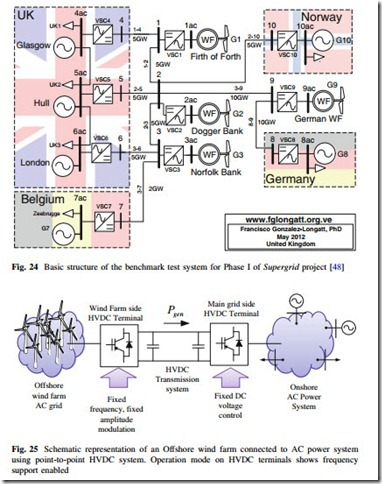
A benchmark test system for the Phase I of Supergrid is introduced on [48], the proposal of such a test system is based on information publicly available on the scenario presented above for 2020–2025.
In this system, the energy from wind generation clusters off the east coast of the UK will be collected at SuperNodes at Firth of Forth, Dogger Bank/Hornsea and Norfolk Bank which will be connected together and interconnected with the German and Belgian North Sea clusters and Norwegian Hydro Power. The net- work then will deliver this power to the existing networks at terminals at Glasgow, Hull and Zeebrugge and nodes at London and Southern Germany (or North Rhine Westphalia)—see Table 3 and Fig. 24.
In order to develop offshore transmission system for this massive international infrastructure, reliability, and security of supply will be the main focus. Among those, fast reactive power response, power reversal, active and reactive power modulation, and fault ride through need to be carefully considered. FR is also another important element, which is done by fast power injection from the DC link, in case of a loss of generation unit at onshore, the frequency may be restored.
Frequency support from wind turbines and wind farms have been described in
previous section, and it has been demonstrated its positive impact on SFR on future power systems. Massive offshore wind farms connected to the grid using HVDC must be enabled to provide frequency support to the AC power system.
Several publications have addressed the issue of frequency support from off- shore wind farms connected via HVDC systems. Most of them based on point-to- point HVDC connections, where the frequency control is enabled by a control loop on the VSC-HVDC stations (see Fig. 25).
Small DC voltage variations are caused by fluctuations of power injected into the DC transmission lines. Hence, by operating the main grid side HVDC terminal
in DC voltage control mode, the wind farm power fluctuations would result in immediate and equal changes in power flow via the DC transmission line. The frequency support of the main AC grid is based on local frequency measurements at the collection grid and the artificial frequency coupling of the collection grid and the main grid is achieved by implementation of DC voltage controllers [55].
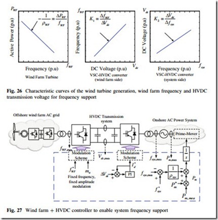
The desired characteristic curves of the wind turbine generation, wind farm frequency and HVDC transmission voltage, are shown in Fig. 26.
The HVDC system is used to create a coupling between wind farm and the AC system, it should be noted that in order to get this desired frequency droop characteristics, the wind turbine should operate with some power margin (or reserve) below the maximum attainable. The schematic of the control strategy including the droop relations is shown in Fig. 27.
Other control schemes reported in the literature including to enable HVDC to delivery in inertial response and primary frequency control [56, 57]. An innovative scheme includes inertia emulation control system using the exercising the electrostatic energy stored in DC shunt capacitors of the HVDC system to emulate inertial contribution [58].
There are several publications that deal with the primary frequency control of multiarea power system considering multiterminal HVDC systems [59, 60].
Almost all of them use a control scheme where DC contributions are used to achieve the primary frequency control. A combination of DC voltage droop control and frequency droop control are used at converter terminals. It allows a bidirectional interaction of multiterminal HVDC and AC grids thereby responding to variations in power unbalances in both systems (as reflected by DC voltage and frequency deviations).
