Wind Integration Dynamic Fault Studies
Model Order Impact on Fault Current or Voltage
The model-related difference in the machine short-circuit behavior is primarily caused by disregarding stator flux transients in the reduced third-order model. However, ignoring the term is only suitable for slow variations and control under limited conditions. It is concluded that the third-order model should not be used for effective fault analysis. The results of the test cases show that the crowbar pro- tection settings also have significant influence on the DFIG short-circuit model. The short-circuit model is useful for grid operator to determine whether it meets the requirements of recently proposed grid codes. Wherever possible, fifth-order model should be used to conclude accurate fault current values. The concept has been discussed in this co-authored publication [12].
Time Step Impact on Fault Current or Voltage
The selection of ideal time step is also a very important factor. If the time step is too short it might result in some abrupt values within one cycle of the electrical frequency and peak current values obtained through such results may cause protective devices to underestimate the fault. This may result in inefficient
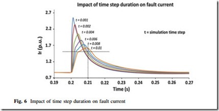
performance of the protective relays. In order to understand the impact of time step on fault current magnitudes for protection configuration, the Type-3 model as discussed above in this chapter was observed under similar network and fault condition scenario. The time step for this simulation was varied from 0.001–0.01 s in a manner illustrated in Fig. 6.
It could clearly be observed that the peak current is directly dependent on the time step duration.Protection relays and devices are configured based on these peak short-circuit currents obtained from simulation results. Thus, in order to assess the protection performance, reasonable time step duration should be selected to improve protection performance. For the above-mentioned case study, time step duration has been selected as t = 0.01 s. This is because of the fact that during 10 ms which is half of the electrical frequency cycle, it is rare that any protection device may detect the fault and fault current would eventually come down to a magnitude shown by crossed dotted lines.
The selection criteria for the time step would be determined by the specific control and protection application of the system. For instance, a system does not consider high magnitude but short-duration current spikes would be less concerned about choosing a shorter time step. Applications requiring/functioning based on high magnitudes even of shorter durations, must catch such peaks, thus requiring a time step to be as short as possible. For HV transmission protection, a shorter time step may be preferred and for a local distribution system a longer time step may be suitable because of its short calculation/simulation duration.
Crowbar Impact on Fault Current or Voltage
Besides the model order type time step duration, other controls within WTG or wind farm may have direct impacts on fault current calculations. A commonly
used and proposed technique is a bypass resistor known as crowbar resistor which is connected to rotor terminal to improve FRT capability for Type-3 which is discussed in several Refs. [13–17]. Bypass technique not only improves the FRT capability but also protects the rotor from being damaged. However, when the crowbar is connected, a Type-3 behaves more like a conventional induction generator, thus compromising the control performance [18, 19]. This technique has its own merits and demerits. While performing the analysis, it is important to identify all the internal controls and protection functions which could interact with your fault current calculations. To explain this phenomenon, Type-3 (DFIG)-based machines having similar network condition and parameters are discussed in Sec- tion 6.1 of chapter ‘‘Probabilistic Modeling and Statistical Characteristics of Aggregate Wind Power’’, where a specific scenario was simulated.
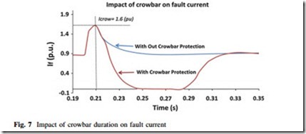
This scenario involves enabling and disabling the crowbar protection within the DFIG model. The crowbar protection was set to operate if the fault current exceeded 1.6 pu in magnitude. Both the fault current profiles for Type-3 machine have been recorded as reported in Fig. 7.
From Fig. 7, it is worth noticing that with crowbar protection the fault current significantly drops down to a negligible value in two electrical frequency cycles. In such cases, Type-3 machines may have severe impacts on protection relay operation during the fault. The details about protection performance in scenarios of ‘with crowbar protection’ and ‘without crowbar protection’ have further been explored in the following sections.
Comparative Fault Analysis for WTGs
In this case study, a three-phase fault on 110 kV busbar has been simulated as indicated in Fig. 5. The fault duration is 400 ms with zero impedance. The purpose of this dynamic fault study is to understand the behaviors of large wind farms with
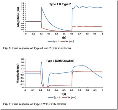
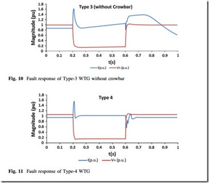
regard to the WTG technology used. Thus, the resultant fault current and voltage from each generator collector bus have been recorded. To understand the responses from each of the wind generator types, similar fault scenarios have been created for each WTG type, while the wind farm is connected to the same PCC. One type of wind farm is connected at a time. The purpose of developing scenarios of weak and independent connections is to investigate the future possibility of having only wind farms connected to PCC, because wind is a resource that is limited to specific parts of geographical regions. If a wind farm of some wind technology isconnected to a grid location then it is very unlikely to have conventional generation in the same region. The fault current contribution and positive sequence voltages have been recorded. The results are illustrated as shown in Figs. 8, 9, 10, and 11.
The normal operations of wind generator types have been well understood. These wind farms may not have a direct impact on each other in the case of normal operation. Their interaction in a case of abnormal operation such as a system fault or any frequency event remains unidentified unless that region faces a similar situation. As FRT criteria are in place it becomes important to investigate these wind farms for system security and voltage stability issues to overcome severe
situations through special protection schemes. Since wind farm interactions may also impact the fault response of any particular wind farm to the system, it is essential to understand a standard response of a generator connected independently to a grid. Based on the simulation results, Fig. 8 represents the pu current and voltage response of Types-1 and 2 WTGs. It is worth noticing that Type-1 and 2 are being treated the same due to the fact that rotor resistance is fixed during simulation. Figures 9 and 10 represent similar responses in pu (per-unit) for Type- 3 with and without crowbar action, respectively. Figure 11 shows the response from Type-4 WTGs.


