Significance of Results
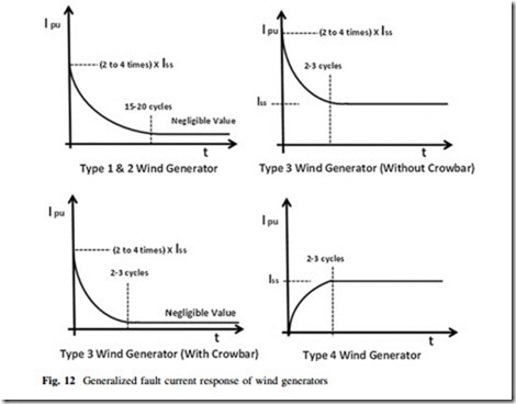
Based on the results obtained from Figs. 8, 9, 10, and 11, the fault response of each generator type can be approximated as shown in Fig. 12.
Type-1 and 2 WTGs have been widely available technologies for large-scale wind units and they are normally modeled as a voltage source behind the locked
rotor impedance. The response is not ideal as a ‘short-circuit’ current source. Typically, the induction generator contributes to the initial three-phases short- circuit current at generator terminals fault, supplying balanced short-circuit cur- rents that normally are 2–4 times the generator rated current. This short-circuit current quickly decays, and typically may be neglected past a few hundred mil- liseconds (300–400 ms) after the short-circuit inception, depending on the size and design of the induction generator. However, Fig. 9 shows that the initial short- circuit current is close to 2.5 times the WTG rated current and decays quickly, similar to the typical induction response.
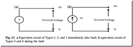
In terms of modeling aspects, Type-1, 2, and 3 WTGs initially behave as a voltage source. Their equivalent circuit can be represented as shown in Fig. 13a. However, after a very short time because of the presence of rotor and grid side converter control action, the response of Type-3 WTG differs from Types-1 and 2 and matches the response of Type-4 WTG which is a constant current source response. At that time, the equivalent circuit of Types-3 and 4 may be represented as shown in Fig. 13b.
Type-3 WTG transient response quickly decays from the initial short-circuit current of a magnitude of 2–4 times the rated current, as a typical squirrel cage
machine, to the limited steady-state current value in the range of 1–1.5 times the generator rated current (Iss). The decaying time is typically a few tens of milli- seconds (40–60 ms). After a few cycles, these WTGs behave as an ideal current source that supplies continuously balanced constant current to the three-phase short-circuit [6]. WTGs equipped with DFIG type respond to the above model only if the generator rotor electronic converter is adequately sized or if the generator system is technically equipped to withstand the short-circuit current without any additional controls such as crowbar action or any special protection scheme in place to trip DFIG to guarantee electronic devices self-protection. However, this may not be true if the DFIG operation is altered by the introduction of crowbar or other control action. If crowbar is activated, Type-3 WTG response matches with Type-2 WTG but fault current decays even faster than Type-2 WTGs. By contrast, DFIG current response as shown in Fig. 12 shows that current reaches a much lower value than the rated value.
Figure 11 shows that Type-4 WTG current builds up to 1.6 times that of the steady-state current but it is worth noticing that it immediately goes back to steady-state value in less than one cycle. This is such a short duration for pro- tection and control activation and so can be ignored here. Such a peak could be due to limitations in modeling full-scale frequency converter-based WTG. It can also be observed in Fig. 11 that fault current through FSFC reaches to a steady value very quickly. This response entirely depends on the converter capability and models being used for dynamic studies. Generally, in case of Type-4 WTG, the initial short-circuit current is around 25 % of the rated current and this builds up in 2–4 cycles to reach a rated value of constant current (Iss) [6].
The next section onward focuses on finding possible issues with relay performance for the various protection types. The most commonly used protection type in case of large wind farms are distance, differential, and overcurrent schemes. These schemes have some minimum sensitivity requirements to detect the fault and operate relays. Most of the modern relays require a minimum current mag- nitude (Imin) to carry out these calculations and operate relay. If the current to the relay is lesser than its minimum required value, relay may not operate and fault could remain unattended.
As mentioned earlier, each WTG is connected to the grid with no conventional generation in the vicinity. In addition, the grid is separated by a long transmission network, thus creating the situation of a weak grid. In such a case, there are two possible issues. If a wind unit does not supply enough fault current as expected, then relay might not operate. Let us examine each of the protection type and their possible issues for all four WTG types. It is worth repeating that the system is a radial one with a single wind farm feeds the fault. The argument revolves around a relay operation where the minimum required current known as pick up current (Ip) is being fed through WTG only.
Type-1 and 2 WTGsProtection Performance
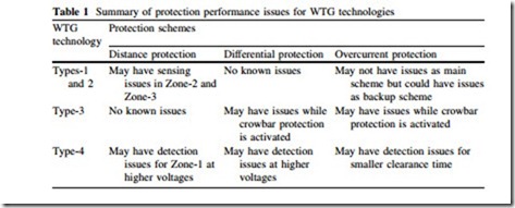
Distance relays operate based on measured impedance value from relaying point to fault location. These impedances are calculated based on ratios of phase to ground voltages of each phase and phase currents. Initial fault current from Type-1 and 2 WTGs is much larger than the rated value so the minimum required or pickup current to operate distance protection is easily achieved; thus, distance relay connected to such wind farms may not have any issues in sensing the fault. However, the fault current decays to a much lower value in a period of a few cycles. This means distance relay for Zone 2 and Zone 3 protections may not adequately function.
Differential protection schemes are not used for all types of transmission levels, being used mostly for HV lines or some of the critical lines. In case of differential protection, Type-1 and 2 WTGs are capable enough to feed in sufficient current at the initial stages of the fault to get protection activated.
For overcurrent protection, Type-1 and 2 WTGs may easily supply enough fault current to get overcurrent relay activated and operated. However, the coordination may be the main concern. Normally, overcurrent protections are used as back-up protection, or if used as main protection, they are delayed to coordinate with differential and distance protection relays, resulting in overcurrent relay waiting for a few hundred milliseconds before the operation. During this waiting period, the fault current of Type-1 and 2 WTGs may have decayed to a much lower value, causing overcurrent protection to fail to operate.
With the presence of FACTS, typically used to improve voltage response, there exist more uncertainties estimating a fault current magnitude of the Types-1 and 2- based wind farms. FACTS devices have some advanced controls which may play a role in achieving fault current response from WTG feeder terminal.
Type-3 WTG Protection Performance
In the absence of crowbar action, distance protection is unlikely to face any issues with Type-3 WTG collective response as the initial current magnitude is large enough to get distance relays operated for Zone-1 protection. After a few cycles, the current response quickly decays to a rated value, capable of achieving Zone 2 and Zone 3 protection activation. Differential protection may not have any prob- lems depending on Type-3 WTG collective response. The initial current should be able to activate the differential protection scheme. However, an overcurrent pro- tection scheme may face issues due to protection coordination delays and the decaying response of such WTGs.
As discussed earlier, this response may be altered through the insertion of a crowbar with the rotor circuit, intentional trips, or any other control/protection action within a WTG. The distance protection, differential protection, and even an overcurrent protection may have detection issues if the crowbar is activated. As shown in Fig. 12, the current response of Type-3 becomes negligible within few cycles as soon as the crowbar action takes place. Either crowbar action is to be delayed or other control strategies used to ensure reliable operation of protection devices. Some turbine manufacturers are employing advanced controls such as advanced grid options 2(AGO2) in VESTAS made turbines. Certain Type-3 WTG may also require FACTS devices having some impact on collective fault current response from collector feeder similar to Type-2 WTG-based wind farms.
Type-4 WTG Protection Performance
If protection schemes are solely dependent on collective current response of Type- 4 WTG, in case of a weak grid situation, then protection operation is an important concern. The initial current response from standard Type-4 WTG is not significant. The fault current magnitude increases within a few tens of milliseconds (30–40 ms) reaching to a value of the rated current magnitude (Iss). If such WTG is not supported through some additional advanced control features then distance, dif- ferential, and overcurrent protection schemes are most likely to have functional problems.
With the response shown in Fig. 11, Type-4 WTG may not be able to supply enough current for Zone-1 protection to operate. Differential protection may also have problems as the fault current may take some time to achieve its rated value, and overcurrent protection may hardly detect the faults because it is difficult to detect normal and abnormal current magnitudes, with the magnitude of fault current supplied by Type-4 WTG.
Nowadays, it is being claimed that modern Type-4 WTGs are far more capable than other wind technologies but these claims are still to be verified through testing and validation for certain fault situations other than simulation platforms. Sig- nificant advancement is not achieved in this direction as unsymmetrical and detailed models of Type-4 WTGs are still awaited to be available for research and study purpose.


