Line Impedances
Overhead lines have resistance and reactance that impedes the flow of cur- rent. These impedance values are necessary for voltage drop, power flow, short circuit, and line-loss calculations.
The dc resistance is inversely proportional to the area of a conductor; doubling the area halves the resistance. Several units are used to describe a conductor’s resistance. Conductivity is often given as %IACS, the percent conductivity relative to the International Annealed Copper Standard, which has the following volume resistivities:
Hard-drawn copper has 97.3%IACS. Aluminum varies, depending on type; alloy 1350-H19 has 61.2% conductivity.
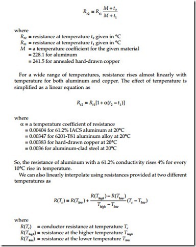
Temperature and frequency — these change the resistance of a conductor. A hotter conductor provides more resistance to the flow of current. A higher frequency increases the internal magnetic fields. Current has a difficult time flowing in the center of a conductor at high frequency, as it is being opposed by the magnetic field generated by current flowing on all sides of it. Current flows more easily near the edges. This skin effect forces the current to flow in a smaller area of the conductor.
Resistance changes with temperature as
With alternating current, skin effects raise the resistance of a conductor relative to its dc resistance. At 60 Hz, the resistance of a conductor is very close to its dc resistance except for very large conductors. Skin effects are much more important for high-frequency analysis such as switching surges and power-line carrier problems. They play a larger role in larger conductors.
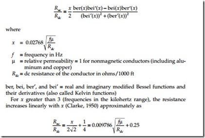
The internal resistance of a solid round conductor including skin effects is [for details, see Stevenson (1962)]:
So, for higher frequencies, the ac resistance increases as the square root of the frequency. For most distribution power-frequency applications, we can ignore skin effects (and they are included in ac resistance tables).
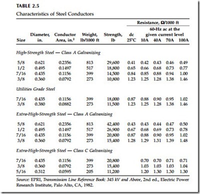
For most cases, we can model a stranded conductor as a solid conductor with the same cross-sectional area. ACSR with a steel core is slightly different. Just as in a transformer, the steel center conductor has losses due to hysteresis and eddy currents. If an ACSR conductor has an even number of layers, the axial magnetic field produced by one layer tends to cancel that produced by the next layer. We can model these as a tubular conductor for calculating skin effect. For odd numbers of layers, especially single-layered conductors like 6/1 or 7/1, the 60-Hz/dc ratio is higher than normal, especially at high current densities. These effects are reflected in the resistances included in tables (such as Table 2.3).
The reactance part of the impedance usually dominates the impedances on overhead circuit for larger conductors; below 4/0, resistance plays more of a role. For all-aluminum conductors on a 10-ft crossarm, the resistance
approximately equals the reactance for a 2/0 conductor. Reactance is pro- portional to inductance; and inductance causes a voltage that opposes the change in the flow of current. Alternating current is always changing, so a reactance always creates a voltage due to current flow.
Distance between conductors determines the external component of reac- tance. Inductance is based on the area enclosed by a loop of current; a larger area (more separation between conductors) has more inductance. On over- head circuits, reactance of the line is primarily based on the separations between conductors — not the size of the conductor, not the type of metal in the conductor, not the stranding of the conductor.
The reactance between two parallel conductors in ohms per mile is:
dab and GMR must have the same units, normally feet. More separation — a bigger loop — gives larger impedances.
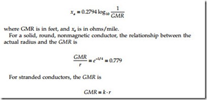
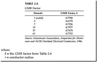
The geometric mean radius (GMR) quantifies a conductor’s internal induc- tance — by definition, the GMR is the radius of an infinitely thin tube having the same internal inductance as the conductor out to a one-foot radius. The GMR is normally given in feet to ease calculations with distances measured in feet. GMR is less than the actual conductor radius. Many conductor tables provide xa, the inductive reactance due to flux in the conductor and outside the conductor out to a one-foot radius. The GMR in feet at 60 Hz relates to xa as:
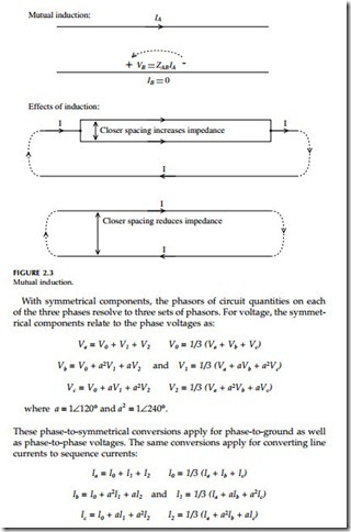
For ACSR conductors (which are layered), the GMR factor is more complicated. Current flowing in a conductor induces a reactive voltage drop on the conductor it is flowing through. By the same induction, current flow in one conductor creates a voltage gradient along parallel conductors (see Figure 2.3). This voltage is of the same polarity as the voltage on the current-carrying conductor. Closer conductors have larger induced voltages. This induction
is significant for several reasons:
• Opposite flow — Current flows more easily when a parallel conductor has flow in the opposite direction. The magnetic field from the other conductor creates a voltage drop that encourages flow in the oppo- site direction. Conductors carrying current in opposite directions have lower impedance when they are closer together.
• Parallel flow — A conductor carrying current in the same direction as a parallel conductor faces more impedance because of the current in the other conductor. Conductors carrying current in the same direction have higher impedance when they are closer together.
• Circulating current — Current flow in the vicinity of a shorted current loop induces currents to circulate in the loop.
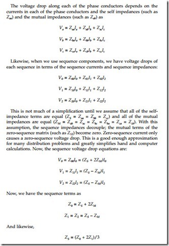
For balanced conditions — balanced voltages, balanced loads, and balanced impedances — we can analyze power systems just with positive-sequence voltages, currents, and impedances. This is regularly done in transmission- planning and industrial load-flow studies. Using just positive-sequence quan- tities simplifies analysis; it’s like a single-phase circuit rather than a three- phase circuit. For distribution circuits, unbalanced loading is quite common, so we normally need more than just positive-sequence parameters — we need the zero-sequence parameters as well. We also need unbalanced analysis approaches for phase-to-ground or phase-to-phase faults.
Note ZS, the self-impedance term. ZS is also the “loop impedance” — the impedance to current through one phase wire and returning through the ground return path. This loop impedance is important because it is the impedance for single-phase lines and the impedance for single line-to- ground faults.
Engineers normally use three methods to find impedances of circuits. In order of least to most accurate, these are:
• Table lookup
• Hand calculations
• Computer calculations
This book provides data necessary for the first two approaches. Table lookups are quite common. Even though table lookup is not the most accurate approach, its accuracy is good enough for analyzing most common distribution problems. Computer calculations are quite accessible and allow easier analysis of more complicated problems.
