AC Motors
Criteria used as guidelines for the application of AC motors are discussed next.
Environmental Conditions
The usual service conditions that a motor is exposed to are the following:
• Ambient temperature not to exceed 40°C and areas with adequate ventilation
• Altitude not to exceed 3300 ft
• Machine installed on a rigid mounting and with belt, chain, or gear drive Unusual service conditions for motor operation or exposure can be listed as the following:
• Combustible, explosive, abrasive, or conducting dust
• Excessively dirty operating conditions where accumulation of dirt will interfere with motor ventilation
• Chemical fumes and explosive or flammable gases
• Abnormal shock, vibration, or mechanical loading from external sources
• High humidity areas, oil vapors, steam, or salt-laden air
• Excessive departure from rated voltage, frequency, or both
• Supply voltage is unbalanced
• Operation above rated speed
• Poor ventilation
Direction of Rotation
Synchronous, universal, single-phase, and nonreversing DC motors have counterclockwise rotation when facing the end of the machine opposite the drive. For AC and DC generators, the rotation is clockwise.
Operation at Altitudes above 3300 ft
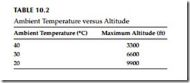
The temperature rises for motors and generators are based on a maximum altitude of 3300 ft with a maximum ambient temperature of 40°C. Motors and generators having a Class A or B insulation system will operate satisfactorily at altitudes above 3300 ft with ambient temperatures as shown in Table 10.2.
Voltage and Frequency
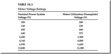
• General-purpose induction and synchronous motors are designed for a rated voltage, frequency, and number of phases. The supply voltage must be known in order to select the correct motor. For AC motors, the motor nameplate voltage will normally be less than the nominal power system voltage, as shown in Table 10.3 for three-phase 60 Hz motors.
• Voltage and frequency variations:
When the voltage at the terminals of a motor varies from nameplate rating, the performance or life of the equipment may be sacrificed. The effect may be serious or minor depending upon the amount the voltage deviates from the nameplate rating. NEMA standards provide a ±10% tolerance from the nameplate rating for operation of induction general-purpose motors. However, even small deviations of voltage from nameplate ratings have an effect on the performance of the motor. The following are some of operating results caused by variations of frequency and voltage.
High voltage on induction motor: The most significant effects of too high a voltage are increased torque, starting current, and heat, and decreased power factor (PF).
Low voltage on induction motor: The most significant effects of too low a voltage are reduced starting torque, increased PF, and increased heating. The increased heating at low voltage and full load reduces the life of the insulation system of the motor.
High and low frequency of induction motor: An increased frequency of the induction motor above the rated frequency will usually improve the PF, decrease locked rotor torque, and increase the speed, friction, and wind- age loss. A decreased frequency below nameplate rating will have the opposite effects. When variations of frequency and voltage occur at the same time, the effects are superimposed. NEMA standards allow a combined voltage and frequency deviation of ±10%.
Voltage unbalance: The voltage supplied to the motor should be equal because voltage unbalance will produce circulating negative sequence currents, which in turn produce heating in the motor. Two to three percent unbalance voltages to the motor will produce the same heating as a 10% overload on the motor. A motor should be derated when the unbalance reaches 4%.
Horsepower, Torque, and Speed Considerations
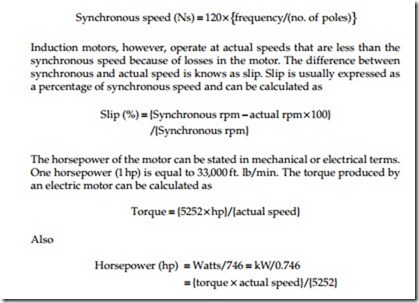
The horsepower of a motor can be defined as the capability of the motor to do a given amount of work. Motors are rated as fractional or integral horsepower. The torque of a motor can be defined as the turning force developed by the motor, or it can be referred to as the resistance offered to the turning force by the driven load. Usually, torque for motors is expressed in terms of percentage of rated full-load torque. The speed of the motor is expressed as rpm, that is, a rate of measure of motion. The several defini- tive speed terms (as outlined in the section on the classification of motors according to variability of speed) that are common to all motors are stan- dardized in order to relate the delivery of torque at a given speed for pur- poses of application. For AC motors the synchronous speed can be calculated as
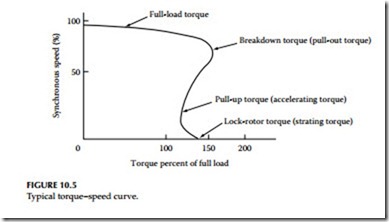
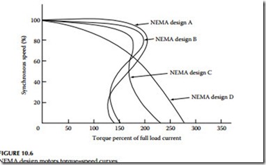
A typical torque–speed curve for a motor is shown in Figure 10.5. The various NEMA design motor torque–speed curves are shown in Figure 10.6.
In order to apply motors, the first thing to determine is the desired full- load speed and the desired horsepower at that speed. Other factors required when applying motors are type of torque required by the load and the starting current limitations. Motor torque characteristics must match those of the load from starting to the time when the motor reaches its rated speed. The motor must develop net accelerating torque for every point on the load curve in order to reach its actual speed.
To understand the torques developed by the various motors, the following definitions are given; they are shown in Figure 10.5 for each design type of motor.
• Lock-rotor torque (starting torque):
The minimum torque developed by the motor for all angular positions of the rotor when the primary winding (stator winding) is energized with AC power supply.
• Accelerating torque:
The torque developed with rated power input during the period from standstill to full speed. This is the net positive torque available to the motor beyond the torque required by the load.
• Breakdown torque (maximum torque):
The maximum torque developed by the motor at rated power input without an abrupt change in speed.
• Pull–out torque:
The maximum torque developed by a motor for 1 min without stalling. It is frequently referred to as the breakdown torque.
• Pull-in torque:
The torque developed during the transition from rated speed (slip speed) to synchronous speed.
• Pull–up torque:
The minimum torque developed with rated power input during the period of acceleration from standstill to rated speed.
• Full-load torque:
power input.
The torque developed at rated speed with rated Torque characteristics of various motors can best be described by comparing one motor type with another. Torques are classified as very high, high, medium, low, and very low. The torque–speed curves for the various NEMA motor designs as listed under classification according to application shown in Figure 10.6.
Power Factor
The connected motor load in a facility is usually a major factor in determining the system PF. Low system PF results in increased losses in the distribution system. Induction motors inherently cause a lagging system PF and, under certain circumstances, they can cause a very low system PF.
The PF of an induction motor decreases as the load decreases. When the load on the motor is increased, the rated load PF increases; that is, a fully loaded motor has a higher PF. Several induction motors, all operating at light load, can cause the electrical system to have a low PF. The PF of induction motors at rated load is less for low-speed than for high-speed motors.
A small increase in voltage (10%) above rated voltage will decrease the PF, and a small decrease in voltage (10%) below rated voltage will improve the PF of an induction motor. However, other performance characteristics may be adversely affected by such a change in voltage. Therefore, operation as close as possible to the nameplate voltage and horsepower ratings is recommended.
The PF of synchronous motors can range from 1.0 to approximately 0 PF leading, depending on the rated PF and the load for which they are built. Standard designs are usually rated for unity, 0.8 lagging, or 0.8 leading PF. As previously stated, synchronous motors have the capability of improving the PF of the electrical system.
Motor Selection
Induction motor: The selection of the induction motor depends on the performance characteristics of the driven machine, and these, in turn, determine the operating characteristics of the motor. Some machines, such as most fans, blowers, centrifugal pumps, and unloaded compressors, require a relatively low starting torque. After starting, the required driving torque increases with increasing speed up to the full-load speed and torque. A design B motor is frequently selected to drive this type of application.
Other machines, such as reciprocating air compressors and loaded conveyors, require high starting torque. The torque needed to start the machine is sometimes greater than the torque required at full-load speed. A design C motor is frequently selected to drive this type of application. For driven machines that impose pulsating loads or require frequent starting of the motor, such as punch press and well pumping, and hoist applications, a design D is often used.
Synchronous motors: In general, large synchronous motors can be applied to any load that induction motors with design B or C characteristics can handle. They have a higher efficiency than an induction motor of the equivalent rating and are capable of improving the system PF. When efficiency is a primary consideration in choosing a relatively large motor, a 1.0 PF synchronous motor may provide the solution. Where system PF improvement is a primary consideration, the use of a 0.8 leading PF synchronous motor may provide the solution.
Multispeed motors: Multispeed motors can be designed to have speed–torque characteristics similar to those of design A, B, C, or D motors of the equiva- lent rating. They can be designed for variable torque, constant torque, or constant horsepower. For the highest efficiency, it is important to select the correct multispeed motor characteristic for the load at all operating speeds. Typical examples of variable-torque loads are fans and centrifugal pumps. Constant-torque motors are used to drive apparatus such as conveyors, positive displacement pumps, and compressors. Machine tools and winches are examples of drives requiring the use of constant-horsepower motors.
