Electrical Switchgear Testing
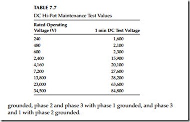
The design of the insulation system for metal-enclosed switchgear is based upon life expectancy of about 30 years. However, environmental conditions such as dirt, moisture, and corrosive atmosphere can shorten the design life. Moisture combined with dirt is the greatest deteriorating factor for insulation systems because of leakage and tracking, which will result in eventual failure. Therefore, it is important to maintain the switchgear insulation and to chart the condition of the primary insulation system by routine testing.
The electrical switchgear may be tested with AC or DC voltage to check the condition of the insulation of switchgear and circuit breakers. Before con- ducting any other tests, an insulation resistance test (Megger) should always be conducted first to determine if it is safe to conduct other HV tests. Also when testing circuit breakers, it is important to check the condition of the circuit breaker contacts and circuit breaker operating mechanism to assure that the circuit breaker is opening and closing as designed. These tests are listed and discussed as follows:
• Insulation resistance test
• DC or AC hi-pot test
• Power factor or dielectric loss test
• Circuit breaker contact resistance test
• Circuit breaker time–travel analysis test
Insulation Resistance Measurement Test
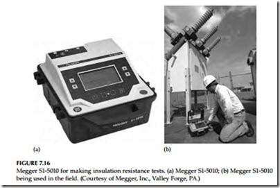
The insulation resistance measurement test may be conducted on all types of electrical switchgear using the insulation resistance megohmmeter com- monly known as the MEGGER.* The Megger S1-5010 is shown in Figure 7.16 that may be used to perform this test.
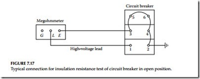
The insulation resistance test consists of applying voltage (600–10,000 V DC) to the apparatus to determine the megohm value of resistance. This test does not indicate the quality of primary insulation. Several factors should be remembered when performing this test. The first is that this test can indicate low values of insulation resistance because of many parallel paths. The other is that an insulation system having low dielectric strength may indicate high resistance values. In view of this, the test results should only be interpreted for comparative purposes. This does not indicate the quality of the primary insulation system from the point of view of dielectric withstandability. The connection diagram for making this test on a power circuit breaker is shown in Figure 7.17. When performing insulation testing, it is recommended that auxiliary equipment, such as potential transformers and lightning arresters, be removed from the stationary switchgear.
Insulation resistance tests are made with the circuit breaker in open and closed position, whereas the insulation test for the switchgear bus is made with one phase to ground at a time, with the other two phases grounded. The procedure for this test is as follows:
• Circuit breaker open:
Connect HV lead to pole 1. Ground all other poles.
Repeat for poles 2 through 6, in turn, with other poles grounded.
• Circuit breaker closed:
Connect HV lead to pole 1 or 2, as convenient,
with either pole of phase 2 and 3 grounded. Repeat for phases 2 and
3 with other phases grounded.
• Stationary gear (buses):
Connect HV lead to phase 1 with phases 2 and
3 grounded. Repeat the same for phases 2 and 3 with other phases
grounded. Also, perform IR tests between phase 1 and 2 with phase 3


