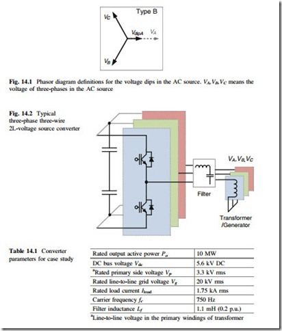
In order to analyze the controllability and performance of power electronics converter under adverse AC source, a severe unbalanced AC voltage is first defined as a case study in this special topic. As shown in Fig. 14.1, the phasor diagram of the three-phase distorted AC voltage is indicated, it is assumed that the type B fault happens with significant voltage dip on phase A of the AC source. Also there are many other types of voltage faults which have been defined as type A–F.
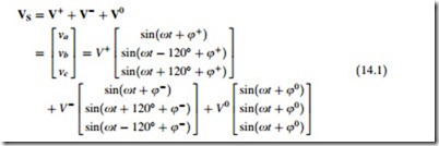
Any distorted three-phase voltage can be expressed by the sum of components in positive sequence, negative sequence, and zero sequence. For simplicity of analysis, only the components with fundamental frequency are considered in this special topic; however it is also possible to extend the analysis to higher order harmonics. The distorted three-phase AC source voltage in Fig. 14.1 can be represented by
where V+, V−, and V0 are the voltage amplitude in positive, negative, and zero sequence, respectively. And φ+, φ−, and φ0 represent the initial phase angles in positive sequence, negative sequence, and zero sequence, respectively. The pre- defined voltage dip as indicated in Fig. 14.1 should contain voltage components in all the three sequences.
A typical used three-phase three-wire two-level voltage source DC-AC converter is chosen and basically designed, as shown in Fig. 14.2 and Table 14.1, where the converter configuration and the parameters are indicated, respectively. It is noted
This chapter is co-authored by F. Blaabjerg and M. Liserre.
aLine-to-line voltage in the primary windings of transformer
that the three-phase AC source is represented here by three windings with a common neutral point, which can be the windings of electric machine or transformer.
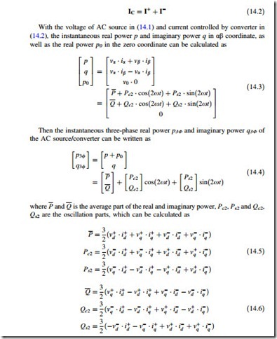
Because there are only three wires and a common neutral point in the windings of AC source, the currents flowing in the three-phases do not contain zero sequence component. As a result, the three-phase load current controlled by the converter can be written as
With the voltage of AC source in (14.1) and current controlled by converter in (14.2), the instantaneous real power p and imaginary power q in αβ coordinate, as well as the real power p0 in the zero coordinate can be calculated as
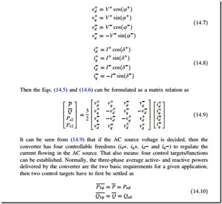
where a positive dq synchronous reference frame and a negative dq synchronous reference frame are applied, respectively, to the positive and negative sequence voltage/current. Each of the component on corresponding positive and negative dq axis can be written as
It is noted that different applications may have different requirements for the control of average power,. E.g., in the power production application, the active power reference Pref injected to the grid is normally set as positive, meanwhile large amount of reactive power Qref may be needed in order to help and to support the grid voltage. As for the electric machine application, the Pref is set as negative for generator mode and positive for motor mode, there may be no or just a few reactive power Qref requirements for magnetizing of electric machine. While in most power quality applications, e.g., STACOM, Pref is normally set to be very small to provide converter loss, and a large amount of Qref is normally required.
Consequently, for the three-phase three-wire converter system, there are only two more current control freedoms left to achieve another two control targets besides (14.10). These two additional control targets may be utilized to further improve the performances of the converter under unbalanced AC source. However, this special topic more focuses the evaluation of control limits and the control possibilities under the whole voltage dipping range. In the following two of the most mentioned control methods achieved by three-wire converter structure are investigated under unbalanced AC source.
A. Elimination of Negative Sequence Current
In most of the grid integration applications, there are strict grid codes to regulate the behavior of the grid connected converters. The negative sequence current which always results in unbalanced load current may be unacceptable from the point view of Transmission System Operator (TSO). Therefore, extra two control targets which aim to eliminate the negative sequence current can be added as
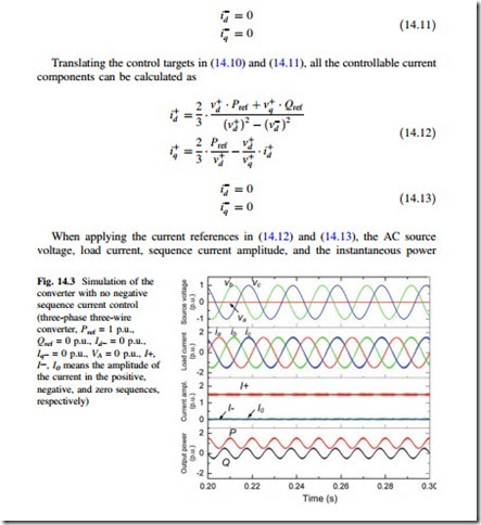
delivered by the converter are shown in Fig. 14.3. The simulation is based on the parameters predefined in Fig. 14.2 and Table 14.1. The AC source voltage is set with VA dipping to zero. The average active power reference Pref for the converter is set as 1 p.u. and reactive power reference Qref is set as 0.
It can be seen from Fig. 14.3 that with the extra control targets in (14.11), there is no zero sequence nor negative sequence component in the load current, i.e., the currents among the three-phases of converter are symmetrical under the given unbalanced AC source condition.
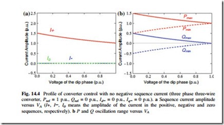
The current amplitude in different sequences and the delivered active/reactive power with relation to the voltage amplitude of the dipping phase VA are shown in Fig. 14.4a, b, respectively. It is noted that only positive sequence current is generated by the converter, and there is up to ±0.5 p.u. oscillations both in the active- and reactive power when VA dips to zero. The significant fluctuation of active power would result in the voltage fluctuation of the DC bus, compromising not only the THD, but also the reliability performances of the converter.
B. Elimination of Active Power Oscillation
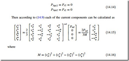
In order to overcome the disadvantage of the active power oscillation under unbalanced AC source, another two extra control targets, which aim to cancel the oscillation items in the instantaneous active power, can be used to replace (14.11) as:
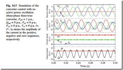
When applying the current references in (14.15), the corresponding source voltage, load current, sequence current, and the instantaneous power delivered by the converter are shown in Fig. 14.5. It can be seen that the active power oscillation at twice of the fundamental frequency can be eliminated.
However, the disadvantage of this control strategy is also significant: First the converter has to deliver up to 3 p.u. load current in the faulty phase, which is much larger than the currents in other two normal phases—this large current may cause over loading of the system and may result in failures. Moreover, significant fluctuation of reactive power will be presented compared to the control strategy in Fig. 14.5. In case of grid connected application, this significant reactive power oscillation may cause grid voltage fluctuation—which is unpreferred especially with weak grid and grid faults.
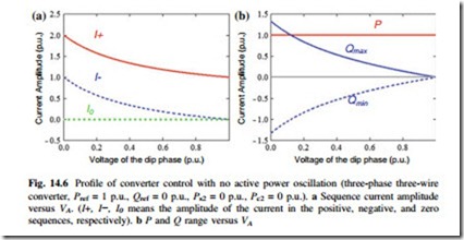
The current amplitude in the different sequences, as well as the delivered active/reactive power with relation to the voltage amplitude on dipping phase is shown in Fig. 14.6a, b, respectively. It is noted that the converter has to deliver both positive and negative sequence current to achieve this control strategy, and up to ±1.3 p.u. oscillation in the reactive power is generated when VA dips to zero.
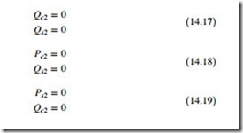
Another three possible control strategies which can eliminate the oscillation of reactive power as shown in (14.17), or reduce the oscillations of both active-and reactive power as shown in (14.18) and (14.19), are also possible for the three-phase three-wire converter under unbalanced AC source
14.1 Conclusion
In a typical three-phase three-wire converter structure, there are four current control freedoms, and it may be not enough to achieve satisfactory performances under unbalanced AC source, because either significantly oscillated power or over-loaded current will be presented.
