Emerging Challenges for Wind Power Converter
Accompanying with the advancements of technology and power capacity, the requirements for WTS are also getting tougher. In this section, some emerging technology challenges for the next generation wind power converters are going to be addressed and summarized.
1.3.1 More Grid Supports
The fluctuated and unpredictable features of wind energy are un-preferred for the power grid operation. Most countries have strict requirements for the behaviors of wind turbines, known as “grid codes” which are updated regularly [14–18]. Basically, the grid codes are always trying to make WTS to act as a conventional power plant from the point view of electrical network. That means the WTS should not only be a passive power source simply injecting available power, but also behave like an active generation unit which can provide frequency/voltage supports for the power grid. Examples of state-of-the-art grid supporting requirements are given in the following—they are specified either for individual wind turbine or for the whole wind farm.
A. Support Under Normal Operation of Grid
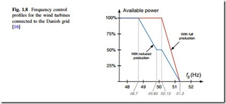
According to most grid codes, the individual wind turbines must be able to control the active power at the Point-of-Common-Coupling (PCC). Normally, the active power has to be regulated based on the grid frequency, e.g., in Denmark, Ireland, and Germany, so that the grid frequency can be somehow maintained. As an example, the characteristic of frequency supports in the Danish grid codes is shown in Fig. 1.8, where the active power should be decreased when the frequency rises above 48.7 or 50.15 Hz depending on the power reserving strategy [16].
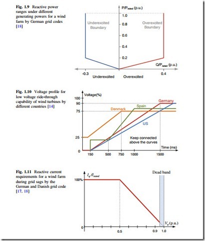
Similarly, the reactive power delivered by the WTS also has to be regulated in a certain range. As shown in Fig. 1.9, both the Danish and German grid codes give a range of the reactive power delivered by WTS against to the active power output. Also the Transmission System Operator (TSO) will normally specify the reactive power range of wind turbine system according to the grid voltage levels; this reactive power control should be realized slowly under the time constant of minutes [14].
B. Supports Under Grid Faults
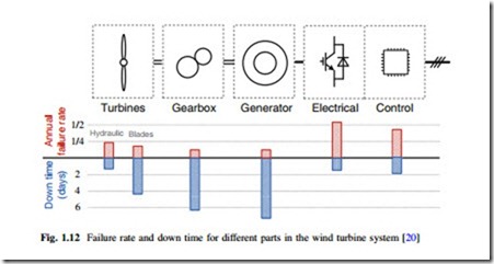
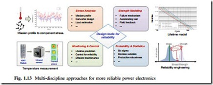
Besides the normal operation, the TSOs in different countries have issued strict supporting requirements for the WTS under grid faults. As shown in Fig. 1.10 [14, 15], in which the boundaries with various grid voltage dipping amplitudes as well as the allowable disturbing time are defined for a wind farm. It is becoming a need that the WTS should meanwhile provide reactive power (up to 100 % current capacity) to contribute to the voltage recovery, when the grid voltage sags are present. Figure 1.11 shows the required amount of reactive current against to the
grid voltage amplitude by German [18] and Danish grid codes [17]. This demand is relatively difficult to be met by some of the old wind turbine concepts like Type A, type B, or even type C, and other power quality units like STACOM may probably be introduced to help the wind turbine system to achieve this tough requirement.
The requirements for more grid supports by wind turbines have on one hand increased the cost per produced kWh, but on the other hand made the wind energy more suitable to be largely utilized and integrated into the power grid. It can be predicted that the stricter grid codes in the future will keep challenging the wind turbine system and pushing forward the power electronics technology.
1.3.2 Higher Reliability
Besides the demands for more grid supports, reliability performance is another emerging problem for the wind turbine system. The dramatic growth in the total installation and individual capacity makes the failures of wind turbines harmful or even unacceptable. The failures of wind turbine system will not only cause stability problems of the power grid due to the sudden absence of large amount of power, but also result in very high cost for repairing and maintenance especially for those large and remotely located wind turbines, which nowadays are becoming popular and dominant [1].
Unfortunately, former field feedbacks have shown that the larger wind turbines seem to be more easily having failures, as indicated in [19]. When looking at the failure rates and down time distribution in individual wind turbine system, as shown in Fig. 1.12, it is obvious that the control and power electronic parts tend to have higher failure rate than the other subsystems with a factor of 2–4 [20]. It is noted that although the generator and gearbox have the largest downtime (i.e., time needed for repair), their failure rates are lower than the electrical and control parts.
As a result, further understanding and improving the reliability of the power electronics converter will be crucial needs for the future wind turbine systems, especially for those large ones at multi-MW level.
The reliability research in power electronics has been carried out for decades and now is moving from a solely statistical approach that has been proven to be unsatisfactory in the automotive industry, to a more physical-based approach which involves not only the statistics but also the investigation and modeling of the root cause behind the failures [21, 22]. As shown in Fig. 1.13, in order to achieve more cost-efficient and reliable power electronics, multi-disciplinary approaches are necessary which involve stress analysis, strength modeling, statistical considerations, and also the online monitoring/control of the converter system. It is noted that a series of reliability design tools may be necessary to transfer, organize, and combine the relevant analysis to more insight reliability performances.
The stress analysis may focus on complete mission profile definition, converter design, stress estimation, and measurement. This group of discipline will target to accurately establish the converter’s loading profile which can trigger the failure mechanisms of critical components, like the thermal cycling in power devices [23], voltage increase in the DC bus [24], vibration, and humidity [25, 26].
The strength modeling may involve the identification, modeling, and accelerating test of failure mechanisms, e.g., the bond wire lift-off and soldering crack inside the power devices [23]. The goal of this group discipline is to seek corre-lations between the established/measured stresses and the quantified fatigues/failures of the critical components.
The monitoring and control approach may relate to the lifetime monitoring [27, 28], stress-relieved controls [29, 30], and intelligent maintenance. This group of discipline will target to monitor and control the converter lifetime during operation. For example, the Collector-Emitter voltage VCE of an IGBT, which is subjected to an accelerated test, experiences a sudden increase just before the IGBT failure [27] and can be used for predictive maintenance in the wind turbine system.
The probability and statistics may add the statistical distribution and correlation to the acquired stress, strength, and component configuration. This group of dis- cipline will target to enhance the robustness of designed converter and take into account the severe usage, six sigma strategies, and quality variations of components in order to give estimation about failure rate in the next 10 years of the product.
It can be seen that the higher reliability requirements will enable many new possibilities and methods to analyze, evaluate, and improve the performances of power electronics, which have not yet been well addressed especially in the wind turbine system.
Special Cost Considerations
The cost issues are the most important considerations which will determine the feasibility of certain energy technologies to be widely utilized in the future. As a typical example, the competitive cost advantage is the main reason why the wind power showed much more significant growth in the last few decades compared to the other renewable energy sources. In order to quantify and compare the cost for different energy technologies, Levelized Cost of Energy (LCOE) index is generally used [31]. LCOE represents the price at which the electricity is generated from a specific energy source over the whole lifetime of the project. It is an economic assessment of the cost of the energy-generating system including all the costs like initial investment, operations and maintenance, cost of fuel, and capital cost. LCOE be defined in a single formula as
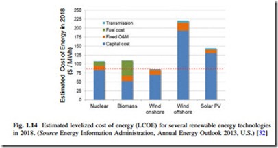
![]() where the Ccap represents the capital cost of the whole generation system, CO&M represents the cost for operation and maintenance during the operating lifetime, and Eannual represents the annual energy production. According to (1.1), it is clear that in order to reduce the energy cost, one effective way is to reduce the capital cost and cost for operation and maintenance; the other effective way is to extend the annual energy production or lifetime of the generation system. Figure 1.14 shows an example of estimated LCOE in the U.S. for several promising renewable energy technologies in 2018 [32]; it can be seen that the cost distribution of different technologies varies a lot and the wind power (onshore) still shows cost advantages against to the other renewable energy sources. It can be also concluded that the capital cost may still be dominant for most of the renewable energy technologies in the next decade.
where the Ccap represents the capital cost of the whole generation system, CO&M represents the cost for operation and maintenance during the operating lifetime, and Eannual represents the annual energy production. According to (1.1), it is clear that in order to reduce the energy cost, one effective way is to reduce the capital cost and cost for operation and maintenance; the other effective way is to extend the annual energy production or lifetime of the generation system. Figure 1.14 shows an example of estimated LCOE in the U.S. for several promising renewable energy technologies in 2018 [32]; it can be seen that the cost distribution of different technologies varies a lot and the wind power (onshore) still shows cost advantages against to the other renewable energy sources. It can be also concluded that the capital cost may still be dominant for most of the renewable energy technologies in the next decade.
As more power electronics are introduced in the energy system to improve the performances of power generation, the cost for the power electronics is becoming more important and it depends a lot on the specific applications. In the wind turbine system, there are also some special cost considerations which impose challenges for the design and the selection of power electronics system.
For instance, the needs for higher power capacity and full-scale power con- version in the wind power application will increase the cost for power semiconductors, passive components, and corresponding cooling management—thereby more efficient circuits and devices are required. Moreover, due to the limited space
in the nacelle or tower, a higher power density will be emphasized and this may lead to extra cost for insulation materials and compact design. Also the weight of the whole converter system should be limited as much as possible because it has to be placed in the nacelle or tower of the wind turbines. The long cable connections between nacelle and tower-base range from dozens to hundreds of meters and may require higher voltage level in the power conversion stage in order to reduce the cable losses. Furthermore remote locations of the wind turbines may increase the cost for installation and maintenance, which also demands high reliability and modularity/redundancy design of the converter system.
It can be expected that these special cost considerations in the wind power application will push the technology limits of power electronics and result in sig- nificantly different approaches for analysis and design of converter compared to the other converter applications.
Formulation of Overall Requirements
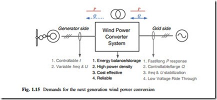
As it can be seen, there are many emerging challenges and design considerations for the next generation wind power converters; these requirements can be generally categorized into the following three groups as also shown in Fig. 1.15:
For the generator side, the current flowing in the generator rotor or stator should be controlled to adjust torque and as a consequence the rotating speed of wind turbine. This will contribute to the active power balance not only in normal oper- ation when extracting the maximum power from the wind turbine, but also in case of grid faults when the generated power needs to be quickly reduced. Moreover, the converter should have the ability to handle variable fundamental frequency and voltage amplitude of the generator outputs.
For the grid side, the converter must comply with the power grid requirements regardless of the wind speed. This means it should have the ability to control the inductive/capacitive reactive power Q delivered into the power grid, and meanwhile perform a fast active power P response. The fundamental frequency as well as voltage amplitude on the grid side should be maintained almost fixed under the normal operation, and the Total Harmonic Distortion (THD) of the current must be restrained at a low level.
Inherently, the converter system needs to be cost effective and to be easy for maintenance, leading to design considerations for high power density, reliability, and modularity. Furthermore, the power converter may need the ability to store some energy, and boost up the voltage level from the generator side to the grid side.
The demands for wind power converter system on one hand reflect the significant penetration of wind energy into the power grid. On the other hand, in order to satisfy these tough requirements, the existing control and design philosophy for power electronics could be changed, resulting in new criteria and methods to evaluate and improve the performances of wind power converter.
