Precautions for start/stop control of AC drives
The protection requirements, for AC VSDs, have already been covered in previous chapters.
The protection of the mains supply side of the converter requires a short-circuit protection. This can be, either in the form of a set of adequately rated fuses, usually as part of a switch-fuse unit, or a main circuit breaker. The stop/start control of the AC drive
can be achieved in a number of ways, mainly:
• Controlling the start/stop input of the converter control circuit
• Breaking the power circuit by means of a contactor.
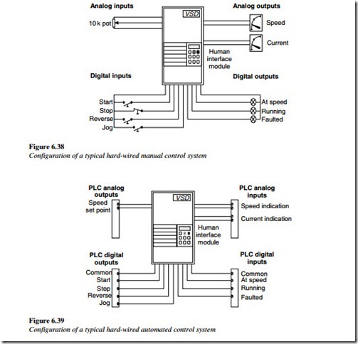
The first is the recommended method, of controlling the stop/start of an AC converter. This may be achieved, by the stop and start pushbuttons being wired directly to the control terminals of the converter, as shown in Figure 6.38. Alternatively, if the control is from a remote device such as a PLC, it can be wired from the PLC directly to the terminals of the AC converter, as shown in Figure 6.39. The second method is, the one most commonly used, for the DOL starting of normal fixed-speed AC motors. Following from the previous DOL ‘standard’ practice, this method is also quite commonly used in the industry for the control of VSDs, particularly for conveyors.
It is usually a safety requirement, to provide an emergency stop or pull-wire switch, to interrupt the power circuit when operated. While this method satisfies the safety
requirements by breaking the power supply to the motor, there are a number of potential hazards with this method of control.
The main problems are:
1. Contactor on supply side of the AC converter
Opening/closing the supply side of the AC converter for stop/start control should be avoided because most modern converters take their power from the DC Bus. Every time the power is removed, the following takes place:
• Power to the control circuit is lost
• Control display goes off
• Diagnostic information disappears
• DC capacitors become discharged
• Serial communication is lost.
When the AC VSD needs to be restarted, there is a time delay (typically 2 s), while the DC Bus charging system completes its sequence to recharge the DC capacitor. This stresses the charging resistors, the DC capacitor, and other components. The charging resistors of many AC converters are short time rated. Although not highlighted in the user
manual, there is a limit to the number of starts that can be done. Many users have the concept of ‘Run on power up’ that is acceptable and unrestricted. The following is an extract from the manual of one of the leading manufacturers of AC converters:
ATTENTION:
The drive is intended to be controlled by, control input signals that will start and stop the motor. A device that routinely disconnects and then reapplies line power to the drive, for the purpose of starting and stopping the motor, is not recommended.
If this type of circuit is used, a maximum of 3 stop/start cycles, in any 5-min period (with a minimum period of 1-min rest between each cycle) is required. These 5-min periods must be separated, by 10-min rest cycles, to allow the drive precharge resistors to cool. Refer to codes and standards applicable, to your particular system, for specific requirements and additional information.
2. Contactor on motor side of the AC converter
Opening/closing the three-phase power circuit, on the motor side of the AC converter, for stop/start control, should also be avoided, while the AC drive is running. Breaking the inductive circuit to the motor produces transient over-voltages, which can damage the IGBTs and other components. Many modern AC converters have RC suppression circuits (snubbers) to protect the IGBTs from this type of switching. The following is an extract from the manual of one of the leading manufacturers of AC converters:
ATTENTION:
Any disconnecting method, wired to the drive output terminals U, V and W must be capable of disabling the drive, if operated during the drive operation.
If opened, during the operation, the drive will continue to produce an output
voltage between U, V and W. An auxiliary contact must be used, to simultaneously disable the drive, or else output component damage may occur. The objective is to ensure, that the AC Converter is OFF before the contacts between the converter and the motor are opened. This will avoid IGBT damage due to transient over-voltages. In addition, closing the motor side contactor, when converter output voltage is present, can result in a motor inrush current, similar to DOL starting. Apart from the stress this places on the converter, the drive will trip on over-current. Repeated attempts at closing the motor contactor after the converter has started, may eventually lead to IGBT failure.
If a contactor has to be installed into the power circuit of an AC Variable Speed Drive system, to meet local safety requirements, then it is better to locate this
contactor downstream of the AC converter. It is then necessary to include, an auxiliary contact on the contactor, which disables the converter control circuit, BEFORE the contactor is opened or closes the enable circuit, AFTER the contactor has been closed. This means that a Late Make-Early Break auxiliary contact, should be used on the contactor and wired to the converter Enable input.
While the above configuration will protect the AC converter from failure, this method of routine stop/start control is NOT recommended. It should be used for “Emergency Stop” conditions only. Routine stop/start sequences should be done from the AC converter control terminals. An alternative method of ensuring that plant operators follow this requirement is, to install a latching relay and a Reset pushbutton. The latching relay needs to be reset after every ‘Emergency Stop’ sequence.
