THEORY OF OPERATION OF REAL SINGLE-PHASE TRANSFORMERS
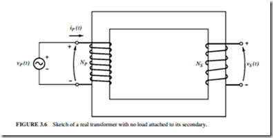
Figure 3.6 illustrates a transformer consisting of two conductors wrapped around a trans- former core. Faraday’s law describes the basis of transformer operation:
where A is the flux linkage in the coil across which the voltage is being induced. Flux link- age A is the sum of the flux passing through each turn in the coil added over all coil turns:
The total flux linkage through a coil is not N (N is the number of turns). This is so because the flux passing through each turn of a coil is slightly different from the flux in the
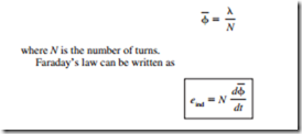
neighboring turns. An average flux per turn is defined. If A is the total flux linkage in all the turns of the coils, the average flux per turn is
Related posts:
Sequence Control
Relays, contactors, and motor starters:Contactors
CELL PHONES:THE CELLULAR CONCEPT
Field effect transistors (Fets):TESTING FETs
Wound Rotor Motors and Manual Speed Control
Work Habits and issues:Workplace ethics
The Essentials of Computer Organization and Architecture - Data Representation in Computer Systems
MOST SEVERE TRANSIENTS (SO FAR)
Part Winding Starters:Overload Protection
HOW MICROCOMPUTERS WORK:DIGITAL SIGNAL PROCESSING
Digital Audio Fundamentals:Error Correction and Concealment
PNEUMATIC CONTROL FUNDAMENTALS:ACTUATORS AND FINAL CONTROL ELEMENTS
Audio Amplifier Performance:AC- and DC-Coupled Amplifiers
ELECTRONIC GADGETS AND HOME APPLIANCES – MODULATION TECHNIQUES

