|
6-36 Draw a diagram of a transformer with subtractive polarity, using ANSI markings. Sec Figure 6-6. |
|
6-3 7 If a transformer is not marked, how could you test it for polarity? Connect the transforrncr as shown in Figure 6-7. If it has subtractive polarity, V will be less than the voltage of the power source; if it has additive polarity, V will be greater than the voltage of the power source. |
|
6-38 What is a split-coil transformer? A transformer that has the coils on the low or high side in separate windings so that they can be connected in series or parallel for higher or lower voltages, as desired. |
 6-39 Draw a diagram of a split-coil transformer with the low side
having split coils for dual voltages; draw an additive polarity transformer, and mark the terminals with ANSI markings. Show the voltages that you use.
See Figure 6-8.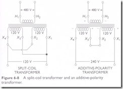
6-40 Draw a diagram of an autotransformer.
See Figure 6-9.
6-41 Where may autotransformers be used?
(a) Where the system being supplied contains an identified grounded conductor that is solidly connected to a similar identified grounded conductor of the system supplying the autotransformer
(see NEC, Sections 210.9 and 450.4); (b) where an autotransformer is used for starting or controlling an induction motor (see NEC, Section 430.82(B)); (c) where an autotransformer is used as
a dimmer, such as in theaters (see NEC, Section 520.25(C)); (d) as part of a ballast for supplying lighting units (see NEC, Section 410.78). Eor voltage bucking and boosting, see NEC, Section
210.9 exception 1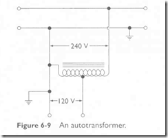
|
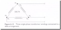
6-44 Draw a schematic diagram of the high-side windings of three single-phase transformers connected in a delta arrangement. Show the ANSI markings. Note that in a delta arrangement, as shown in figure 6-12, H 1 is connected to H2 of the next transformer, and so on. |
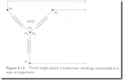
 6-45 Draw a schematic diagram of the high-side windings of three single-phase transformers connected in a wye (Y) arrangement.
Show the ANSI markings.
Note that in a wye arrangement, as shown in Figure 6-13, all of the His are connected in common, and the Hjs each supply one phase wire.
