Let us consider first a sinusoidal airgap flux density in the airgap, at no load (zero rotor currents). Making use of Ampere’s law we get, for airgap flux amplitude,
![]() Bg1 ≈ 0gK K1c phases ; Ks >1 where F1 is the phase mmf/pole amplitude,
Bg1 ≈ 0gK K1c phases ; Ks >1 where F1 is the phase mmf/pole amplitude,
(5.114)
![]() ( )F1 phase = 2W I1 0 πp21K Kq1 y1
( )F1 phase = 2W I1 0 πp21K Kq1 y1
For a three-phase machine on no load, (5.115)
µ ( )F
![]() F1m = 3WI1 0 π2p1K Kq1 y1 (5.116)
F1m = 3WI1 0 π2p1K Kq1 y1 (5.116)
Now the flux per pole, for the fundamental Φ1, is
So the airgap flux linkage per phase (a = 1) Ψ11h is
ψ11h = W K1 q1K y1Φ1 (5.118)
The magnetization inductance of a phase, when all other phases on stator and rotor are open, L11m is
= 11h = 0 (WK K1 q1 y1)2 Leτ ψ 4µ
![]() L11m I 2 π2 p gK K1 c s (5.119)
L11m I 2 π2 p gK K1 c s (5.119)
0
Ks–total saturation factor.
In a similar manner, for a harmonic ν, we obtain
L11mν = 4µ0 (WK K1π2qν yν)2 p gK K1 Lecτ sν ; Ksν ≈ (1 1.2− ) (5.120)
The saturation coefficient Ksν tends to be smaller than Ks, as the length of harmonics flux line in iron is usually shorter than for the fundamental. Now, for three-phase supply we use the same rationale, but, in the (5.114) F1m will replace (F1)phase.
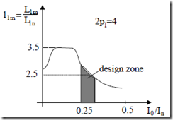
L1mν = 6µ0 (W K Kπ ν12 q2ν yν)2 p gK K1 Lecτ sν (5.121) When the no-load current (Io/In) increases, the saturation factor increases, so the magnetization inductance L1m decreases (Figure 5.25).
L1m = 0 1π2q1 y1 p gK K I /I1 cLes ( 0 n )
In general, a normal inductance, Ln, is defined as (5.122)
Vn, In, ω1n rated phase voltage, current, and frequency of the respective machine. Well designed induction motors have l1m (Figure 5.25) in the interval 2.5 to 4; in general, it increases with power level and decreases with large number of polesLn = Vωn :l1m = L1m (5.123)
Figure 5.25 Magnetization inductance versus no load current I0/In
It should be noticed that Figure 5.25 shows yet another way (scale) of representing the magnetization curve.
The magnetization inductance of the rotor L22m has expressions similar to (5.119) – (5.120), but with corresponding number of turns phase, distribution, and chording factors.
However, for the mutual magnetising inductance between a stator and rotor phase L12m, we obtain
L12mν = 4πµ20 (W K1 qνsKyνsW K2 qνrKyνrKcνr )p gK1Leτsν (5.124)
This time, the skewing factor is present (skewed rotor slots). From (5.124) and (5.120),
LL1211mmνν = W K2W KqνrKνsyKνryKνscνr (5.125)
1 q
It is now evident that for a rotor cage, Kqνr = Kyνr = 1 as each bar (slot) may be considered as a separate phase with W2 = ½ turns.
The inductance L11m or L22m are also called main (magnetization) self inductances, while L1m is called the cyclic (multiphase supply) magnetizing inductance. In general, for m phases,
L1m = m2 L11m ; m = 3 for three phases (5.126)
Example 5.1. The magnetization inductance L1m calculation
For the motor M1 geometry given in the previous paragraph, with doublelayer winding and Ns = 36 slots, Nr = 30 slots, 2p1 = 4, y/τ = 8/9, let us calculate L1m and no-load phase current I0 for a saturation factor Ks = 2.6 and Bg1 = 0.9T, Kst = Ksr = 1.8, Kc = 1.3 (Figure 5.20, 5.21).
Stator (rotor) slot opening are: bos = 6g, bor = 3g, W1 = 120turns/phase, Le = 0.12m, and stator bore diameter Di/2= 0.051m.
Solution
• The Carter coefficient Kc ((5.4), (5.3)) is
= τs,r = 1.280 (5.127) Kc1,2 τs,r − γ1,2 ⋅g / 2 1.0837 τ =s πNDs1 = π⋅ ⋅2 0.36 051 = 9.59 10⋅ −3m (5.128)
γ1 = 5(2+2bb2osb/ gos/ g/ g))22 = 512+62122 ==3.8.2747 (5.129)
γ 2 = 5+ 2orbor / g = 5+ 6
Kc = Kc1 ⋅Kc2 =1.280⋅1.0837 =1.327 (5.130)
• The distribution and chording factors Kq1, Ky1, (5.100), (5.103) are
(5.132)
• The no load current I0 from (5.114) is
L 6
So the no load phase current I0 is
I0 = 3.12A
Let us consider rated current In = 2.5I0.
• The emf per phase for f1 = 60Hz is
(5.134)
E1 = 2πf L1 1mI0 = 2π60⋅0.1711⋅3.12 = 201.17V
With a rated voltage/phase V1 = 210 V, the relative value of L1m is
(5.135)
(5.136)
V /1 1In 210/ 2 60 2.5 3.12
It is obviously a small relative value, mainly due to the large value of saturation factor Ks = 2.6 (in the absence of saturation: Ks = 1.0).
In general, E1/V1 ≈ 0.9 – 0.98; higher values correspond to larger power machines.
